Three-phase half-wave Cycloconverters
advertisement
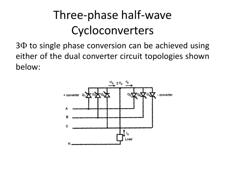
Three-phase half-wave Cycloconverters 3 to single phase conversion can be achieved using either of the dual converter circuit topologies shown below: A Thevenin equivalent circuit for the dual converter is shown next slide: The input and output voltages are adjusted to be equal and the load current can flow in either direction. Thus, V0 Vd Vd 0 cos p Vd 0 cosn where Vd0 is the dc output voltage of each converter at zero firing angle and p and N are the input and output firing angles. For a 3 halfwave converter Vd0 =0.675VL and Vd0 = 1.35VL for the bridge converter (VL is the rms line voltage). Voltage-tracking between the input and output voltages is achieved by setting the sum of the firing angles to . Positive or negative voltage polarity can be achieved as shown below: A 3 to 3 cycloconverter can be implemented using 18 thyristors as shown in next slide: Each phase group functions as a dual converter but the firing angle of each group is modulated sinusoidally with 2/3 phase angle shift -> 3 balanced voltage at the motor terminal. An inter-group reactor (IGR) is connected to each phase to restrict circulating current. An output phase wave is achieved by sinusoidal modulation of the thyristor firing angles. A variable voltage, variable frequency motor drive signal can be achieved by adjusting the modulation depth and output frequency of the converter. Cycloconverter Circuits for Three-phase Output A 3 to 3 bridge cycloconverter (widely used in multi-MW applications) can be implemented using 36 thyristors as shown below: The output phase voltage v0 can be written as: v0 2V0 sin 0t where V0 is the rms output voltage and 0 is the output angular frequency. We can also write: v0 Vd 0 cos p Vd 0 cosn m f Vd 0 sin 0t where the modulation factor, mf is given by: m f 2V0 / Vd 0 From these equations, we can write: p cos [m f sin 0t ] 1 and N P Thus for zero output voltage, mf=0 and P= N= /2. For max. phase voltage, mf=1 => P=0, N= . See below figure for P and N values for mf=0.5 and 1. The phase group of a cycloconverter can be operated in two modes: 1) Circulating current mode 2) Non-circulating current (blocking) mode In the circulating current mode, the current continuously circulates between the +ve and ve converters. Although the fundamental output voltage waves of the individual converters are equal, the harmonics will cause potential difference which will result in shortcircuits without an IGR


