ZIF-Clip® Headstage Adapters
advertisement

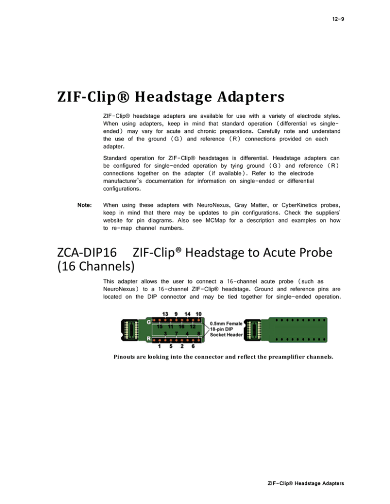
12-9 ZIF‐Clip®HeadstageAdapters ZIF-Clip® headstage adapters are available for use with a variety of electrode styles. When using adapters, keep in mind that standard operation (differential vs singleended) may vary for acute and chronic preparations. Carefully note and understand the use of the ground (G) and reference (R) connections provided on each adapter. Standard operation for ZIF-Clip® headstages is differential. Headstage adapters can be configured for single-ended operation by tying ground (G) and reference (R) connections together on the adapter (if available). Refer to the electrode manufacturer’s documentation for information on single-ended or differential configurations. Note: When using these adapters with NeuroNexus, Gray Matter, or CyberKinetics probes, keep in mind that there may be updates to pin configurations. Check the suppliers' website for pin diagrams. Also see MCMap for a description and examples on how to re-map channel numbers. ZCA‐DIP16 ZIF‐Clip® Headstage to Acute Probe (16 Channels) This adapter allows the user to connect a 16-channel acute probe (such as NeuroNexus) to a 16-channel ZIF-Clip® headstage. Ground and reference pins are located on the DIP connector and may be tied together for single-ended operation. Pinoutsarelookingintotheconnectorandreflectthepreamplifierchannels. ZIF-Clip® Headstage Adapters 12-10 System 3 ZCA‐OMN16 ZIF‐Clip® Headstage to Chronic Probe (16 Channels) This adapter connects a 16-channel chronic Omnetics based probe to a 16-channel ZIF-Clip® headstage. Ground and reference pins may be tied together for singleended operation. Pinoutsarelookingintotheconnectorandreflectthepreamplifierchannels. ZCA‐OMN32 ZIF‐Clip® Headstage to Chronic Probe (32 Channels) This adapter connects a 32-channel chronic Omnetics based probe to a 32-channel ZIF-Clip® headstage. By default, the inputs are single ended, with Ref and GND tied together. A jumper is provided to give the user the option of making the inputs differential. To make the inputs differential, cut the jumper between ground and reference (shown below). Pinoutsarelookingintotheconnectorandreflectthepreamplifierchannels. ZIF-Clip® Headstage Adapters System 3 12-11 ZCA‐NN32 ZIF‐Clip® Headstage to 32 Channel Acute Probe) This adapter connects a 32-channel acute NeuroNexus probe to a 32-channel ZIFClip® headstage. Note: X (Ref) is a reference pin that is connected from the adapter to the probe only. See the jumper configuration below for more information. Pinoutsarelookingintotheconnectorandreflectthepreamplifierchannels. ZCA‐EIB32 ZIF‐Clip® Headstage to Electrode Interface Board (32 Channels) This adapter allows the user to connect 32 channels of electrode wire to a 32channel ZIF-Clip® headstage. Ground and reference. Wires can be soldered to holes or connected using EIB pins, such as the large EIB tapered pins available from NeuraLynx. To guard against noise pickup, the lengths of any additional wires should be minimized and the wires should be bundled together to avoid creating open loops that can pick up inductive interference. Specifications: Hole diameter: Row Spacing: .3 mm 0.69 mm from center to center ZIF-Clip® Headstage Adapters 12-12 System 3 ZCA‐EIB32PinoutandDimensionsDiagram(TopView) ZCA‐NN64 ZIF‐Clip® Headstage to 64 Channel Acute Probe) This adapter connects a 64-channel acute NeuroNexus probe to a 64-channel ZIFClip® headstage. Note: X (Ref) is a reference pin that is connected from the adapter to the probe only. See the jumper configuration below for more information. Pinoutsarelookingintotheconnectorandreflectthepreamplifierchannels. ZIF-Clip® Headstage Adapters System 3 12-13 Jumper Configuration The following table describes the jumper configurations for both the ZCA-NN32 and ZCA-NN64. Jumper Connections G R Operation Shorts headstage Ground and Reference inputs together, yielding single-ended amplification of signals relative to ground. X (Ref) G R X (Ref) G R X (Ref) Shorts headstage Reference input to the pin labeled X (a low impedance site on the probe) yielding differential amplification of signals relative to the voltage of the X (Ref) site. Headstage Ground and Reference separated and X (Ref) pin is not used, yielding differential amplification of signals relative to the voltage of the Reference ZCA‐GM60 ZIF‐Clip® Headstage to 60‐Channel Chronic Probe This adapter connects a 60-channel chronic Gray Matter microdrive (SC60-1) to a 64-channel ZIF-Clip® headstage. Ground and reference pins are located on the adapter for access to single-ended and differential modes of operation. See the diagram below for connection details. Pinoutsarelookingintotheconnectorandreflectthepreamplifierchannels. ZIF-Clip® Headstage Adapters 12-14 System 3 Gray Matter Microdrive (SC60-1) ZCA-GM60 Adapter ZCA‐GM60ConnectionDiagram ZCA‐OMN96 ZIF‐Clip® Headstage to 96‐Channel Omnetics Probe This adapter connects a 96-channel chronic omnetics connector to a 96-channel ZIF-Clip® headstage. For single-ended operation, tie Com (ground) and IND (indifferent reference) together. Pinoutsarelookingintotheconnectorandreflectthepreamplifierchannels. ZIF-Clip® Headstage Adapters System 3 12-15 Use jumper to choose which reference (R1, R2, R3) to use for all channels. Only one reference may be selected. ZCA‐CK96A ZIF‐Clip® Headstage to 96‐Channel Chronic Probe This adapter connects a 96-channel chronic CyberKinetics CerePort connector to a 96-channel ZIF-Clip® headstage. For single-ended operation, tie the ground and reference pins (shown in diagram) together. Pinoutsarelookingintotheconnectorandreflectthepreamplifierchannels. ZIF-Clip® Headstage Adapters 12-16 System 3 Headstage Adapter CerePort Plug ZCA‐CK96AConnectionDiagram. A four-pin header located on the backside of the adapter is provided for access to two probe reference pins. These pins are separate references and are connected internally to the adapter. Connecting a jumper between the headstage reference pins (Ind) and either of the probe reference pins (Ref1 or Ref2) connects the headstage reference to the desired probe reference (see table below for more information). Jumper Configuration The following table describes the jumper configurations for the ZCA-CK96A. Jumper Connections Operation Ind Headstage Ground and Reference separated and Ref1, Ref2 pins are not used, yielding differential amplification of signals relative to the voltage of the Reference (Ind). An external connection for the headstage reference (Ind) must be used for differential amplification. Ref1 Ind Ref2 Ind Ref1 Ind Ref2 Ind Ref1 Ind Ref2 ZIF-Clip® Headstage Adapters Shorts headstage Reference input (Ind) to the pin labeled Ref1 (a low impedance site on the probe) yielding differential amplification of signals relative to the voltage of the Ref1 site. Shorts headstage Reference input (Ind) to the pin labeled Ref2 (a low impedance site on the probe) yielding differential amplification of signals relative to the voltage of the Ref2 site. System 3 12-17 ZCA‐ICS96 ZIF‐Clip® Headstage to 96‐Channel Chronic Probe This adapter connects a 96-channel acute CyberKinetics ICS-96 connector to a 96channel ZIF-Clip® headstage. Banks A, B and C are labeled on the adapter and can be matched with the ICS-96 electrode sockets for correct alignment when plugging the two together. A four-pin header located on the top of the adapter is provided for access to the REF1 and REF2 probe reference pins used by the ICS-96. Connecting a jumper between the headstage reference pins (IND) and either of the probe reference pins (REF1 or REF2) connects the headstage reference to the desired probe reference (see table below for more information). For single-ended operation, solder the headstage ground (COM) and headstage reference (IND) solder points together. Jumper Configuration The following table describes the jumper configurations for the ZCA-ICS96. Jumper Connections Operation IND Headstage Ground and Reference separated and REF1, REF2 pins are not used, yielding differential amplification of signals relative to the voltage of the Reference (IND). An external connection for the headstage reference (IND) must be used for differential amplification. IND REF1 REF2 IND REF1 IND REF2 ND REF1 IND REF2 Shorts headstage Reference input (IND) to the pin labeled REF1 (a low impedance site on the probe) yielding differential amplification of signals relative to the voltage of the REF1 site. Shorts headstage Reference input (IND) to the pin labeled REF2 (a low impedance site on the probe) yielding differential amplification of signals relative to the voltage of the REF2 site. ZIF-Clip® Headstage Adapters 12-18 System 3 Pinouts Pinoutsarelookingintotheconnectorandreflectthepreamplifierchannels. ZCA‐UP16 16‐Channel Plextrode® U‐Probe to ZIF‐Clip headstage This adapter connects an 8 or 16-channel acute Plextrode® U-Probe connector to a 16-channel ZIF-Clip® headstage. The adapter includes mounting holes for attachment to a micromanipulator. Configuration for single-ended or differential operation is provided on the electrode. Refer to the Plextrode documentation for jumper configurations. Pinoutsarelookingintotheconnectorandreflectthepreamplifierchannels. ZIF-Clip® Headstage Adapters System 3 12-19 ZCA‐UP24 24‐Channel Plextrode® U‐Probe to ZIF‐Clip headstage This adapter connects a 24-channel acute Plextrode® U-Probe connector to a 32channel ZIF-Clip® headstage. The adapter includes mounting holes for attachment to a micromanipulator. Configuration for single-ended or differential operation is provided on the electrode. Refer to the Plextrode documentation for jumper configurations. Pinoutsarelookingintotheconnectorandreflectthepreamplifierchannels. ZCA‐MIL16 ZIF‐Clip® Headstage to Mill‐Max connector (16 Channels) This adapter connects a 18-channel Mill-Max based probe to a 16-channel ZIFClip® headstage. By default, the inputs are single ended, with Reference (R) and Ground (G) tied together. A jumper is provided to give the user the option of making the inputs differential. To make the inputs differential, sever the jumper trace on the board between R and G (shown below). Jumper Trace Pinoutsarelookingintotheconnectorandreflectthepreamplifierchannels. Mill-Max Connector Specifications: Pitch: 0.050" (1.27 mm) Row Spacing: 0.050" (1.27 mm) ZIF-Clip® Headstage Adapters 12-20 System 3 ZCA‐MIL32 ZIF‐Clip® Headstage to Mill‐Max connector (32 Channels) This adapter connects a 32-channel Mill-Max based probe to a 32-channel ZIFClip® headstage. By default, the inputs are single ended, with Reference (R) and Ground (G) tied together. A jumper is provided to give the user the option of making the inputs differential. To make the inputs differential, cut the jumper between R and G (shown below). Pinoutsarelookingintotheconnectorandreflectthepreamplifierchannels. Mill-Max Connector Specifications: Pitch: 0.050" (1.27 mm) Row Spacing: 0.050" (1.27 mm) ZIF-Clip® Headstage Adapters System 3 12-21 ZCA‐VD8 ZIF‐Clip® Headstage to Versa Drive connector (32 Channels) This adapter connects a Versa Drive (Versa-8 Optical) via two Mill-Max connectors to a 32-channel ZIF-Clip® headstage. 18-Socket Mill-Max Connectors Match notch to ensure correct orientation. Pinoutsarelookingthroughtheconnectorandreflectthepreamplifierchannels. Mill-Max Connector Specifications: Pitch: 0.050" (1.27 mm) Row Spacing: 0.050" (1.27 mm) Connector to Connector Specification: Pitch: 0.236" (6 mm), Pin 1 to Pin 18 ZIF-Clip® Headstage Adapters 12-22 ZIF-Clip® Headstage Adapters System 3


