L957 instructions
advertisement

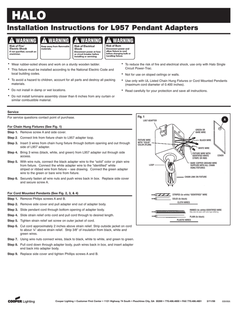
HALO Installation Instructions for L957 Pendant Adapters • • Wear rubber-soled shoes and work on a sturdy wooden ladder. This fixture must be installed according to the National Electric Code and local building codes. • To avoid a hazard to children, account for all parts and destroy all packing materials. • • Do not install in damp or wet locations. • To reduce the risk of fire and electrical shock, use only with Halo Single Circuit Power-Trac. • • Not for use on sloped ceilings or walls. • Read carefully for your protection and save all instructions. Use only with UL Listed Chain Hung Fixtures or Cord Mounted Pendants (maximum cord diameter of 0.400 inches). Do not install luminaire assembly closer than 6 inches from any curtain or similar combustible material. Service For service questions contact point of purchase. Fig. 1 A L957 ADAPTER For Chain Hung Fixtures (See Fig. 1) GREEN OR BARE WIRE Step 1. Remove screw A and side cover. Step 2. Connect link from fixture chain to L957 adapter loop. Step 3. Insert 3 wires from chain hung fixture through bottom opening and out through side of L957 adapter. FIXTURE WIRE WITH “SOLID” COLOR (PLAIN) BLACK WIRE WHITE WIRE Step 4. Bring 3 wires (black, white, and green) from L957 adapter out through side access. Step 5. With wire nuts, connect the black adapter wire to the “solid” color or plain wire from fixture. Connect the white adapter wire to the “identified” white striped or ribbed wire from fixture – see drawing. Connect the green adapter wire to the green or bare wire from fixture. Step 6. Securely fasten all wire nuts and push wires back in box. Replace side cover and secure screw A. For Cord Mounted Pendants (See Fig. 2, 3, & 4) Step 1. Remove Philips screws A and B. Step 2. Remove side cover and pull adapter end out of adapter body. Step 3. Slide pendant cord through bottom opening of adapter body. Step 4. Slide strain relief onto cord and pull cord through to desired length. Step 5. Tighten strain relief set screw on outer jacket of cord. FIXTURE WIRE WITH IDENTIFIED WHITE STRIPE OR RIBS COVER BARE COPPER GROUND WIRE SUPPLIED WITH ALL CHAIN HUNG FIXTURES LOOP CHAIN LINK ON FIXTURE STRIPED (to white) “IDENTIFIED” WIRE SOLID (to black) CLOTH WIRES RIBBED (to white) IDENTIFIED WIRE May also be plain with wire type lettering PLAIN (to black) PLASTIC WIRES Step 6. Cut cord approximately 2 inches above strain relief. Strip outside jacket on cord to about ¼” above strain relief. Strip 3/8” of insulation from black, white and green wires. Step 7. Using wire nuts connect wires, black to black, white to white, and green to green. Step 8. Pull cord down through adapter body, push wires back in box, and insert adapter end back into adapter body. Step 9. Replace side cover and tighten Phillips screws A and B. Cooper Lighting • Customer First Center • 1121 Highway 74 South • Peachtree City, GA 30269 • 770.486.4800 • FAX 770.486.4801 3/11/08 698496A HALO Fig. 3 Fig. 2 3/8” ADAPTER END 2” 1/4” OUTSIDE JACKET STRAIN RELIEF C Fig. 4 A B ADAPTER BODY ASSEMBLED ADAPTER BOX COVER PLATE To Install Unit on Track (See Fig. 5, 6, & 7) Step 1. Insert Pendant Adapter into track (Fig. 5). Step 2. Locate Cover Plate on adapter and Track Polarity Line. Depress Thumb Latch and twist adapter approximately ¼ turn (90°) until latch locks into track opening. Note: Forcing the adapter in the wrong direction may damage the contact assembly. If adapter will not turn easily, twist adapter in the opposite direction. Cover Plate on adapter must be on the opposite side as the Track Polarity Line for proper installation (Fig. 6). To Remove Unit from Track (Fig 7) Step 1. Depress Thumb Latch until latch is free of track opening. Twist adapter ¼ turn (90°) until contact head is free (Fig 7). Step 2. Remove adapter from track. Fig. 5 Fig. 6 Fig. 7 POLARITY LINE Cooper Lighting • Customer First Center • 1121 Highway 74 South • Peachtree City, GA 30269 • 770.486.4800 • FAX 770.486.4801 3/11/08 698496A


