ms424a Manual - Fire-Lite Alarms by Honeywell
advertisement
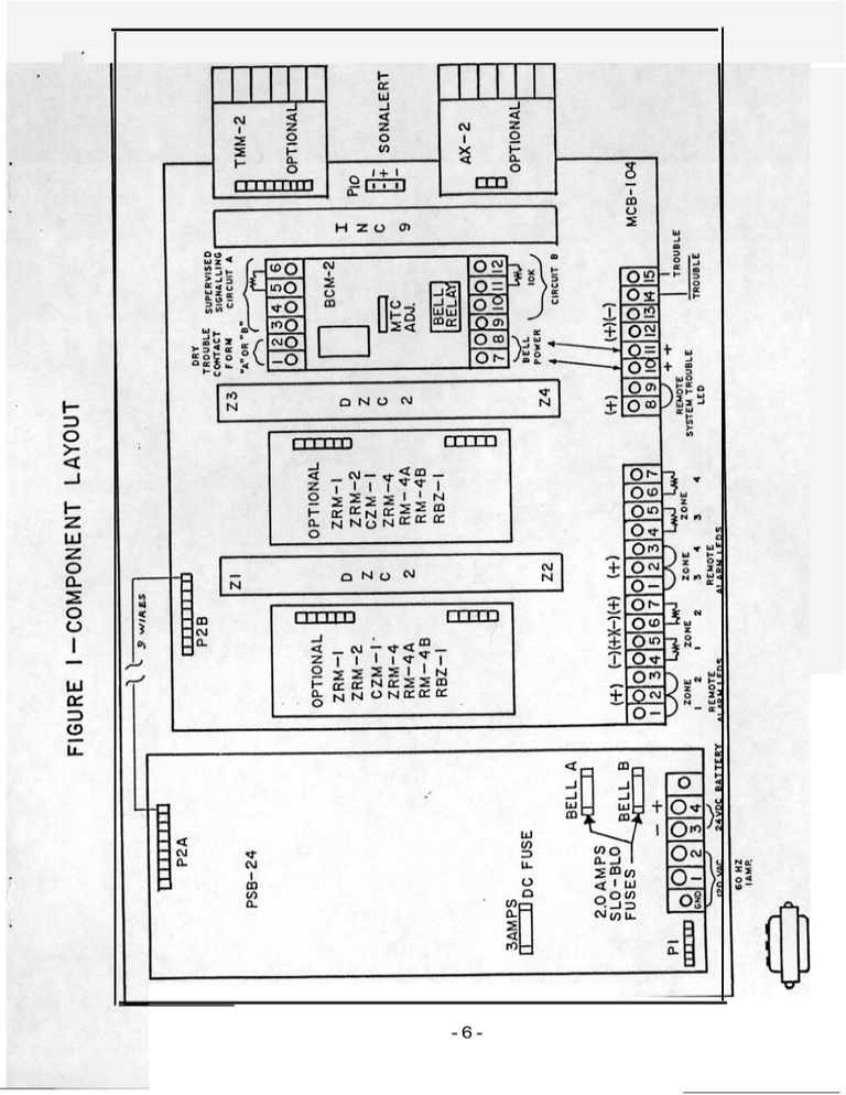
-6- INITIATING DEVICE CONNECTION (TYPICAL) FIGURE 3 SUPERVISED CLASS B OPERATION ELR 4.7K 0 . SMOKE DETECTOR HEAT DETECTOR -u MANUAL STATION 3 -. SMOKE DETECTOR + 4 5 6 7 (-) (+) (-) (+) ZONE I Notes: 1) MCB- 104 ZONE 2 Compatible, U.L. listed, 2 wire detector available from Fire-Lite, include the following series: CP101 SD12T SD32T CP204 CP311 CP711 CP751 Maximum detector current: 2.0mA./Zone Detection loop specifications 8) Operation: Class B Voltage standby: 23VDC Alarm current: 15mA minimum. Short circuit current: .35MA±10ma. Supervision current: 5mA End of line resistor: 4.7k, 5% Maximum loop resistance: 200 ohms Smoke and ionization detectors requiring separate 24VDC can be powered from MCB-104 terminal 12(+) & 13(-) . Use end of line relay (SDLR-B) to supervise power circuit wiring. 3 ) Detector loop current is sufficient to ensure operation of one detector per zone. 4 ) Compatible, U.L. listed, 2 wire detector available from Fire-Lite. ‘ 5 ) Initiating devices include: Manual station, heat detectors, smoke detectors, ionization detectors, waterflow alarm devices, coded manual stations. 6) Use mechanical water motor gong if waterflow alarm devices are connected to the zone. 7) Inhibit latching circuit by removing diode marked with a * from DZC-2 card if coded manual stations are connected. 2) -5- RZA REMOTE ZONE ANNUNCIATOR FIGURE 12 CONNECTION DIAGRAM (-) TO TERMINAL 13 OF MCB-1O4 ZONE 4 3 ZONE 2 - SYSTEM TROUBLE + 24v TROUBLE , TROUBLE SCHEMATIC ZONE ALARM LEDS SYSTEM TROUBLE LED - ’ TROUBLE --( . SILENCE SWITCH - Notes: field connections are supervised for opens except sonalert. check normally open connection flip Trouble silence switch’ its off-normal (downward) position. Sonalert should sound. not check connection between MCB terminal 14 & terminal 8 RZA. 2,’ Maximum wire resistance is 100 ohms for all connections except connection to terminal 7 should not exceed 5 ohms. Silenced audible device will resound when trouble condition 3) is corrected. 1) All* * To to If of -18-
