Chapter 4, Problem 32. Use source transformation to find ix in the
advertisement
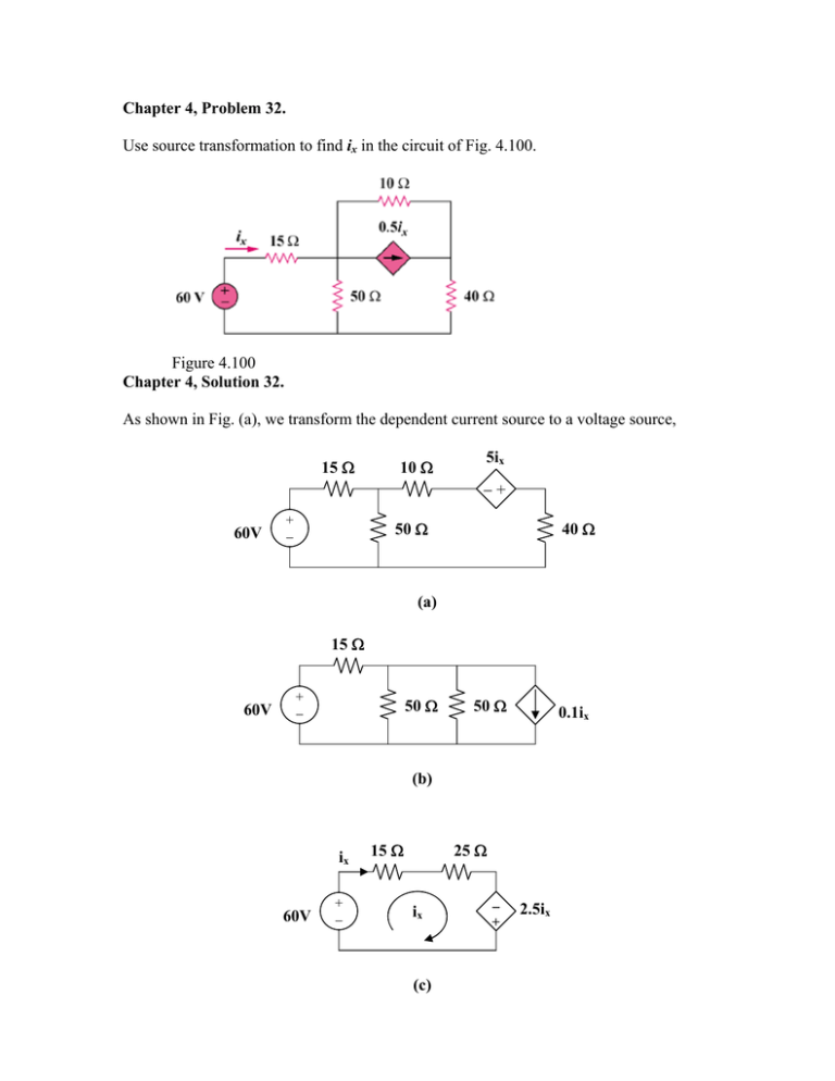
Chapter 4, Problem 32. Use source transformation to find ix in the circuit of Fig. 4.100. Figure 4.100 Chapter 4, Solution 32. As shown in Fig. (a), we transform the dependent current source to a voltage source, 15 Ω 10 Ω 5ix −+ 60V + − 50 Ω 40 Ω (a) 15 Ω 60V + − 50 Ω 50 Ω 0.1ix (b) ix 60V + − 15 Ω 25 Ω ix (c) − + 2.5ix In Fig. (b), 50||50 = 25 ohms. Applying KVL in Fig. (c), -60 + 40ix – 2.5ix = 0, or ix = 1.6 A Chapter 4, Problem 33. Determine RTh and VTh at terminals 1-2 of each of the circuits of Fig. 4.101. Figure 4.101 Chapter 4, Solution 33. (a) RTh = 10||40 = 400/50 = 8 ohms VTh = (40/(40 + 10))20 = 16 V (b) RTh = 30||60 = 1800/90 = 20 ohms 2 + (30 – v1)/60 = v1/30, and v1 = VTh 120 + 30 – v1 = 2v1, or v1 = 50 V VTh = 50 V Chapter 4, Problem 39. Obtain the Thevenin equivalent at terminals a-b of the circuit in Fig. 4.106. 1A 10 Ω 16 Ω c a 10 Ω 8V 5Ω + _ c b Figure 4.106 For Prob. 4.39. Chapter 4, Solution 39. We obtain RTh using the circuit below. 10 Ω 5Ω 10 Ω RTh = 16 + 20 // 5 = 16 + 16 20 x5 = 20 Ω 25 RTh To find VTh, we use the circuit below. 1A 10 + 10 Ω 8V 16 V2 V1 + + _ V2 5 VTh _ _ At node 1, [(V1–8)/10] – 1 + [(V1–V2)/10] = 0 or 2V1 – V2 = 18 (1) At node 2, [(V2–V1)/10] + [(V2–0)/5] + 1 = 0 or –V1 + 3V2 = –10 Adding 3(1) to (2) gives 5V1 = 44 or V1 = 8.8 V Using (2) we get 3V2 = 8.8 – 10 = –1.2 or V2 = –400 mV. Finally, VTh = V2 + (–1)(16) = –0.4 – 16 = –16.4 V \ (2) Chapter 4, Problem 44. For the circuit in Fig. 4.111, obtain the Thevenin equivalent as seen from terminals (a) a-b (b) b-c Figure 4.111 Chapter 4, Solution 44. (a) For RTh, consider the circuit in Fig. (a). RTh = 1 + 4||(3 + 2 + 5) = 3.857 ohms For VTh, consider the circuit in Fig. (b). Applying KVL gives, 10 – 24 + i(3 + 4 + 5 + 2), or i = 1 VTh = 4i = 4 V 3Ω 3Ω 1Ω a 2Ω b (a) a + VTh 4Ω 24V + − RTh 4Ω 5Ω + − 1Ω 2Ω i b 10V 5Ω (b) (b) For RTh, consider the circuit in Fig. (c). 3Ω 1Ω 4Ω 3Ω b 24V 2Ω RTh 5Ω 1Ω 4Ω vo + − b + 2Ω 5Ω 2A c (c) VTh c (d) RTh = 5||(2 + 3 + 4) = 3.214 ohms To get VTh, consider the circuit in Fig. (d). At the node, KCL gives, [(24 – vo)/9] + 2 = vo/5, or vo = 15 VTh = vo = 15 V Chapter 4, Problem 47. Obtain the Thèvenin and Norton equivalent circuits of the circuit in Fig. 4.114 with respect to terminals a and b. 50 V Figure 4.114 Chapter 4, Solution 47 Since VTh = Vab = Vx, we apply KCL at the node a and obtain 50 − VTh VTh = + 2VTh ⎯ ⎯→ VTh = 250 / 126 = 1.9841 V 12 60 To find RTh, consider the circuit below. 12 Ω Vx a 60 Ω 2Vx 1A At node a, KCL gives V V 1 = 2V x + x + x ⎯ ⎯→ V x = 60 / 126 = 0.4762 60 12 V V I N = Th = 1.9841 / 0.4762 = 4.167 A R Th = x = 0.4762Ω, R Th 1 Thus, VTh = 1.9841 V, Req = RTh = RN = 476.2 mΩ, IN = 4.167 A Chapter 4, Problem 48. Determine the Norton equivalent at terminals a-b for the circuit in Fig. 4.115. 4 4A Figure 4.115 Chapter 4, Solution 48. 8 To get RTh, consider the circuit in Fig. (a). 10Io 42 Ω +− 10Io 42 Ω +− + Io 84 Ω + Io V − 1A − 4A (a) From Fig. (a), VTh 84 Ω (b) Io = 1, 4 – 10 +8 – V = 0, or V = 2 RN = RTh = 2/1 = 2 ohms To get VTh, consider the circuit in Fig. (b), Io = 4, VTh = -10Io + 8Io = –8 V IN = VTh/RTh = -8/2 = -4A Chapter 4, Problem 51. Given the circuit in Fig. 4.117, obtain the Norton equivalent as viewed from terminals (a) a-b (b) c-d Figure 4.117 Chapter 4, Solution 51. (a) From the circuit in Fig. (a), RN = 4||(2 + 6||3) = 4||4 = 2 ohms RTh 6Ω VTh + 6Ω 4Ω 3Ω 2Ω 120V 4Ω + − 3Ω 6A 2Ω (b) (a) For IN or VTh, consider the circuit in Fig. (b). After some source transformations, the circuit becomes that shown in Fig. (c). + VTh 2Ω 40V + − 4Ω i 2Ω 12V + − (c) Applying KVL to the circuit in Fig. (c), -40 + 8i + 12 = 0 which gives i = 7/2 VTh = 4i = 14 therefore IN = VTh/RN = 14/2 = 7 A (b) To get RN, consider the circuit in Fig. (d). RN = 2||(4 + 6||3) = 2||6 = 1.5 ohms 6Ω 2Ω 4Ω i + 3Ω 2Ω (d) RN VTh 12V + − (e) To get IN, the circuit in Fig. (c) applies except that it needs slight modification as in Fig. (e). i = 7/2, VTh = 12 + 2i = 19, IN = VTh/RN = 19/1.5 = 12.667 A Chapter 4, Problem 53. Find the Norton equivalent at terminals a-b of the circuit in Fig. 4.119. Figure 4.119 Chapter 4, Solution 53. To get RTh, consider the circuit in Fig. (a). 0.25vo 0.25vo 2Ω 2Ω a + 6Ω 3Ω + vo 2Ω 1A − 1/2 a 1/2 vo vab − 1A − b b (a) + (b) From Fig. (b), vo = 2x1 = 2V, -vab + 2x(1/2) +vo = 0 vab = 3V RN = vab/1 = 3 ohms To get IN, consider the circuit in Fig. (c). 0.25vo 6Ω 2Ω a + 18V + − 3Ω vo Isc = IN − b (c) [(18 – vo)/6] + 0.25vo = (vo/2) + (vo/3) or vo = 4V But, (vo/2) = 0.25vo + IN, which leads to IN = 1 A Chapter 4, Problem 59. Determine the Thevenin and Norton equivalents at terminals a-b of the circuit in Fig. 4.125. Figure 4.125 Chapter 4, Solution 59. RTh = (10 + 20)||(50 + 40) 30||90 = 22.5 ohms To find VTh, consider the circuit below. i1 i2 10 Ω 20 Ω + VTh 8A 50 Ω 40 Ω i1 = i2 = 8/2 = 4, 10i1 + VTh – 20i2 = 0, or VTh = 20i2 –10i1 = 10i1 = 10x4 VTh = 40V, and IN = VTh/RTh = 40/22.5 = 1.7778 A Chapter 4, Problem 66. Find the maximum power that can be delivered to the resistor R in the circuit in Fig. 4.132. Figure 4.132 Chapter 4, Solution 66. We first find the Thevenin equivalent at terminals a and b. We find RTh using the circuit in Fig. (a). 2Ω 10V − + 3Ω 2Ω a b + 3Ω a VTh 5Ω b RTh + − 5Ω 20V − + i 30V (a) (b) RTh = 2||(3 + 5) = 2||8 = 1.6 ohms By performing source transformation on the given circuit, we obatin the circuit in (b). We now use this to find VTh. 10i + 30 + 20 + 10 = 0, or i = –6 VTh + 10 + 2i = 0, or VTh = 2 V p = VTh2/(4RTh) = (2)2/[4(1.6)] = 625 m watts Chapter 4, Problem 73. Determine the maximum power that can be delivered to the variable resistor R in the circuit of Fig. 4.139. Figure 4.139 Chapter 4, Solution 73 Find the Thevenin’s equivalent circuit across the terminals of R. 10 Ω 25 Ω RTh 20 Ω 5Ω RTh = 10 // 20 + 25 // 5 = 325 / 30 = 10.833Ω 10 Ω + 60 V - 25 Ω + + Va - 20 Ω VTh - + 5Ω Vb - 20 (60) = 40, 30 − Va + VTh + Vb = 0 Va = 2 p max 5 (60) = 10 30 ⎯ ⎯→ VTh = Va − Vb = 40 − 10 = 30 V Vb = V 30 2 = Th = = 20.77 W 4 RTh 4 x10.833

