Global In-place Analysis of WTIV Leg for Korean West-South
Journal of Ocean and Wind Energy (ISSN 2310-3604)
Copyright © by The International Society of Offshore and Polar Engineers
Vol. 2, No. 2, May 2015, pp. 121–127; http://dx.doi.org/10.17736/jowe.2015.jcr25
http://www.isope.org/publications/publications.htm
Global In-place Analysis of WTIV Leg for Korean West-South Offshore Wind Zone
Tae-Min Cho, Joo-Shin Park, Yeong-Su Ha, Bong-Jae Kim and Ki-Bok Jang
Central Research Institute, Samsung Heavy Industries, Co., Ltd.
Geoje-Si, Gyeongsangnam-Do, Korea
In this study, a global in-place analysis of the WTIV (Wind Turbine Installation Vessel) leg for the Korean west-south offshore wind zone is performed through Finite Element Analysis (FEA). The environmental conditions and seabed characteristics of the Korean west-south offshore wind zone are first collected and investigated through direct measurements and literature surveys. Based on these data, the design specifications are established and the overall basic design is performed. The dynamic characteristics of the WTIV for the Korean west-south offshore wind zone are considered in the global in-place analysis of the leg, and the stability against the Overturning Moment (OTM) is analyzed. The structural integrity of the WTIV leg is verified through code checks, and the adequate safety margin is observed. The results of this study can be expected to be practical and useful data for the design of the WTIV for the Korean west-south offshore wind zone.
INTRODUCTION
In order to prepare for global warming and shortages of fossil fuels, the Korean government has planned to develop an offshore wind zone located at the west-south part of the Korean Peninsula.
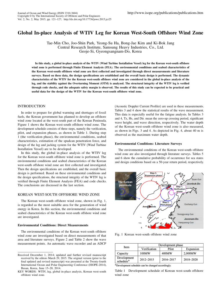
Figure 1 shows the Korean west-south offshore wind zone. The development schedule consists of three steps, namely the verification, pilot, and expansion phases, as shown in Table 1. During step
1 (the verification phase), the environmental conditions, seabed characteristics, estimation of the spudcan penetration force, and design of the leg and jacking system for the WTIV (Wind Turbine
Installation Vessel) are to be developed.
In this study, the global in-place analysis of the WTIV leg for the Korean west-south offshore wind zone is performed. The environmental conditions and seabed characteristics of the Korean west-south offshore wind zone are first collected and investigated.
Then the design specifications are established, and the overall basic design is performed. Based on these environmental conditions and the design specifications, the structural integrity of the WTIV leg is verified through Finite Element Analysis (FEA) and code checks.
The conclusions are discussed in the last section.
KOREAN WEST-SOUTH OFFSHORE WIND ZONE
The Korean west-south offshore wind zone, shown in Fig. 1, is regarded as the most suitable area for the generation of wind energy in Korea. In this section, the environmental conditions and seabed characteristics of the Korean west-south offshore wind zone are investigated.
Environmental Conditions: Direct Measurements
The environmental conditions of the Korean west-south offshore wind zone are investigated based on direct measurements of that area and literature surveys. Figure 2 and Table 2 show the wave measurement points. An automatic wave recorder and an ADCP
(Acoustic Doppler Current Profiler) are used in these measurements.
Tables 3 and 4 show the statistical results of the wave measurement.
This data is especially useful for the fatigue analysis. In Tables 3 and 4, Tz, Hs, and Dir. mean the zero-up crossing period, significant wave height, and wave direction, respectively. The water depth of the Korean west-south offshore wind zone is also measured, as shown in Figs. 3 and 4. As depicted in Fig. 4, about 40 m is observed as the maximum water depth.
Environmental Conditions: Literature Surveys
The environmental conditions of the Korean west-south offshore wind zone are also investigated through literature surveys. Tables 5 and 6 show the cumulative probability of occurrence for sea states and design conditions based on a 50-year return period, respectively.
Fig. 1 Korean west-south offshore wind zone
Received December 1, 2014; updated and further revised manuscript received by the editors March 29, 2015. The original version (prior to the final updated and revised manuscript) was presented at the Twenty-fourth
International Ocean and Polar Engineering Conference (ISOPE-2014),
Busan, Korea, June 15–20, 2014.
KEY WORDS: WTIV, leg, global in-place analysis, Korean west-south offshore wind zone.
Table 1 Development schedule of Korean west-south offshore wind zone
122 Global In-place Analysis of WTIV Leg for Korean West-South Offshore Wind Zone
Table 4 Statistical results of wave measurement (II)
Fig. 2 Wave measurement points
Table 2 Wave measurement points
These data are obtained from the Korea Institute of Ocean
Science & Technology (KIOST) report (Korea Institute of Ocean
Science & Technology, 2005). The design conditions for each return period for the Korean west-south offshore wind zone, which were studied by Jeong et al. (2012), are summarized in Table 7.
The design conditions for the wind velocity are determined to be
41 m/sec based on the literature surveys (Lee et al., 2009).
Seabed Characteristics
The seabed characteristics of the Korean west-south offshore wind zone are investigated through direct measurements and literature surveys. Figure 5 shows the measurement points for the seabed
Fig. 3 Measured area for water depth characteristics. In Fig. 5, eight points (NO.1-NO.8) have been measured by the Korea Electric Power Research Institute (Korea
Electric Power Research Institute, 2011). Other points (OW.1-OW.8
and OWW.1-OWW.8) have been measured by the authors through the national project acknowledged at the end of this study.
Figure 6 shows the seabed characteristics of the measurement points. In the standard penetration test, the N value, shown in
Fig. 6, is the number of hammer strikes required to drive the split spoon sampler into the soil to a certain depth. The N value is generally corrected based on the experimental conditions such as the hammer and sampler efficiency. In Fig. 6, the measured points
NO.1-NO.4, NO.6, OW.3, OW.4, and OW.8 show stable seabed characteristics, whereas there is the possibility of a punch-through at the measured points NO.5, NO.7, NO.8, OW.1, OW.2, OW.5-
Table 3 Statistical results of wave measurement (I) Fig. 4 Results of water depth
Journal of Ocean and Wind Energy, Vol. 2, No. 2, May 2015, pp. 121–127 123
Table 5 Cumulative probability of occurrence for sea state (Korea
Institute of Ocean Science & Technology, 2005)
(a) NO.1-NO.8 (Korea Electric Power Research Institute, 2011)
Table 6 Design conditions based on 50-year return period (Korea
Institute of Ocean Science & Technology, 2005)
OW.7, and OWW.1-OWW.8. Table 8 shows the soil properties at the measured points NO.1 and NO.8 (Korea Electric Power
Research Institute, 2011). In Table 8, , c u
, and 0 represent the angle of internal friction for the sand, submerged unit weight, and undrained shear strength, respectively. These data are required to estimate the spudcan penetration force.
Spudcan Penetration Force
In the design of the jack-up or WTIV, the estimation of the spudcan penetration force is an important step. So far, many studies have been performed on the design of the spudcan and the spudcan penetration force (Cho et al., 2012, 2013; Merifield et al., 2003,
2006; Purwana, 2006; Purwana et al., 2009; Sloan and Kleeman,
1995). In this study, the spudcan penetration force for the Korean west-south offshore wind zone is estimated based on the SNAME rule (Society of Naval Architects and Marine Engineers, 2002).
The SNAME rule is widely accepted in offshore engineering, and the conservative results are obtained through the SNAME rule.
The spudcan penetration force has already been studied by Cho et al. (2013). Figure 7 shows the spudcan penetration force at the measured points NO.1 and NO.8, respectively (Cho et al., 2013).
The spudcan is assumed to be a flat, circular, cross-sectional area of 100 m 2 with height of 2 m. At the measured point NO.1,
(b) OW.1-OW.8
(c) OWW.1-OWW.8
Fig. 6 N value vs. penetration depth curve the seabed can resist about 14,000 tons without the punch-through phenomenon occurring. However, at the measured point NO.8, the seabed can resist only 1,500 tons and then the punch-through phenomenon occurs. The estimated spudcan penetration force can be useful and practical data for the design of the spudcan.
Fig. 5 Measurement points for seabed characteristics
Table 7 Design conditions for each return period (Jeong et al.,
2012)
124 Global In-place Analysis of WTIV Leg for Korean West-South Offshore Wind Zone
Table 8 Soil properties of Korean west-south offshore wind zone
Table 9 Total leg length
(a) NO.1 point
Fig. 8 Composition of total leg length the maximum water depth. However, 55 m of the water depth is selected for the design of the total leg length, with a consideration of some design margin. Figure 8 shows the composition of the total leg length described in Table 9.
Table 10 shows the design specifications of the transit and DP
(dynamic positioning), preloading, crane operation, and survival conditions. Among all the conditions, the survival condition is generally the most severe case for the majority of the structures.
The maximum wave height and wind velocity are determined to be
13.76 m and 41 m/sec for the survival condition, respectively.
(b) NO.8 point
Fig. 7 Spudcan penetration force
DESIGN SPECIFICATIONS AND OVERALL BASIC
DESIGN OF THE WTIV FOR KOREAN WEST-SOUTH
OFFSHORE WIND ZONE
The environmental conditions and seabed characteristics have been investigated through direct measurements and literature surveys.
Based on these data, the design specifications and overall basic design of the WTIV for the Korean west-south offshore wind zone are determined. In the basic design, a four-leg type of WTIV is considered. The total leg length is determined to be 105 m, as shown in Table 9. The air gap is determined to be 9.0 m based on the environmental conditions. In Fig. 4, 40 m is observed as Table 10 Design specifications of WTIV
Journal of Ocean and Wind Energy, Vol. 2, No. 2, May 2015, pp. 121–127 125
*LCG (longitudinal center of gravity), TCG (transverse center of gravity), VCG (vertical center of gravity)
**CD (drag coefficient), CM (inertia coefficient)
Table 11 Parameters for the strength analysis of WTIV leg
GLOBAL IN-PLACE ANALYSIS OF WTIV LEG FOR
KOREAN WEST-SOUTH OFFSHORE WIND ZONE
Preparation of Strength Analysis for WTIV Leg
In order to perform the global in-place analysis of the WTIV leg, all kinds of engineering data, such as the main dimension of the WTIV leg, analysis parameters, material properties, allowable stresses, and loading conditions (static and dynamic components),
Fig. 9 One bay of leg structure are required. The parameters for the strength analysis of the WTIV leg are summarized in Table 11. The material properties and allowable stresses are summarized in Tables 12 and 13, respectively.
In Table 13, the code checks are calculated based on the ARI RP
2A-WSD 21st criterion for the tubular members such as the brace and the AISC 13th criterion for the nontubular members such as the chord and rack. The leg property data are depicted in Table 14.
Figure 9 shows one bay of the WTIV leg structure.
Strength Analysis
In the strength analysis, the following methodologies are applied:
• All the members in the leg structure are modeled as beam elements. The hull is idealized as a grillage, and equivalent properties of the hull are assigned.
• The members forming the leg-to-hull connection are modeled as axial compressive elements with respective initial gaps between the rack and gear distance.
• The spudcans are modeled as rigid beams connecting the leg chords to the pinned support that is at half the depth of the spudcan penetration.
• The gravity loads, such as the self-weight of the legs, lightship weight, and payload, are applied to the structure. The lightship weight and payload are applied as uniform loads, and global moments are applied to correct the Center of Gravity (CG) of the applied loads.
• The basic environmental loads are applied to the structure in various combinations with the gravity loads.
• The structure is analyzed under the applied loads, with the
Pã large deflection effect being taken into account.
Table 12 Material property of WTIV leg
Table 13 Allowable stress
Table 14 Leg property data Fig. 10 SACS model of WTIV leg for strength analysis
126 Global In-place Analysis of WTIV Leg for Korean West-South Offshore Wind Zone
Fig. 11 Flow chart of strength analysis of WTIV leg
• 7% damping is assumed on the basis of the SNAME T&RB
5-5A guidelines (Society of Naval Architects and Marine Engineers,
2002).
• The structure is also checked for the available factor of safety against overturning on the basis of the DNV-RP-C104 recommended practice (DNV, 2011).
The flow chart of the global in-place analysis of the WTIV leg is shown in Fig. 11. During the first step of the calculation, the static results, such as of both the base shear and Overturning
Moment (OTM) at the end of the spudcan, are estimated. Then the natural frequency based on the SDOF (Single Degree Of Freedom) model is estimated during the second step of the calculation. The
Dynamic Amplification Factor (DAF) is defined by the use of the classical method based on the previous results depending on the wave heading angles. After these procedures, a reanalysis is performed to consider the newly updated inertia loads.
The strength analysis of the WTIV leg is performed with the use of Structural Analysis Computer System (SACS) software and code checks. The SACS model of the WTIV leg for the strength analysis is shown in Fig. 10. The considered loading conditions in the global in-place analysis of the WTIV leg are shown in Table 15.
Table 15 Loading conditions in global in-place analysis of the
WTIV leg
A total of four cases of loading directions are considered, as shown in Fig. 12. The pinned conditions are applied at the spudcan. For all the considered loading conditions, the results of the unity check for all the members satisfy the allowable value. The maximum combined unity check plot is shown in Fig. 14. The 0.75 of the maximum value of the unity check is calculated, and it can be said that the structural integrity of the WTIV leg is verified through the code checks.
Table 16 and Fig. 13 show the overturning stability calculation and the factor of safety against the overturning, respectively. The
1.97 of the minimum safety factor is calculated, and it is seen that
*SMRF: stabilizing moment reduction factor (stabilizing moment = M so
-
SMRF)
4 1 5 Allowable safety factor: 1.05
Table 16 Overturning stability calculation
Fig. 12 Four cases of loading directions Fig. 13 Factor of safety against overturning
Journal of Ocean and Wind Energy, Vol. 2, No. 2, May 2015, pp. 121–127
Fig. 14 Maximum combined unity check (UC) plot the designed WTIV leg has enough of a safety margin against the overturning moment. The safety margin against the overturning moment is calculated based on the DNV-RP-C104 recommended practice (DNV, 2011).
CONCLUSIONS
The Korean government has planned to develop an offshore wind zone located at the west-south part of the Korean Peninsula. The development schedule consists of three steps, namely the verification, pilot, and expansion phases. In order to develop the Korean westsouth offshore wind zone, the WTIV for this wind zone is required to install the wind turbines within the schedule. Therefore, the basic design of the WTIV and the global in-place analysis of the WTIV leg are important factors for these development steps.
In order to perform the global in-place analysis of the WTIV leg, the environmental conditions and seabed characteristics of the Korean west-south offshore wind zone are investigated and collected through both direct measurements and literature surveys.
Based on these data, design specifications are established and the overall basic design is performed. The global in-place analysis of the WTIV leg for the Korean west-south offshore wind zone is performed through beam element analysis with code checks. It is seen that the designed WTIV leg has sufficient safety margin against the overturning moment, and the structural integrity of the WTIV leg is verified through code checks. The results of this study can be expected to provide practical and useful data for the development of the Korean west-south offshore wind zone.
ACKNOWLEDGEMENTS
This work was supported by the New & Renewable Energy of the Korea Institute of Energy Technology Evaluation and Planning
127
(KETEP) grant (No. 20123010020090), which was funded by the
Ministry of Knowledge Economy of the Government of South Korea.
REFERENCES
Cho, TM, An, DY, Kim, BJ, Jang, KB, and Kang, KS (2013).
“Practical Estimation of Spudcan Penetration Force for Korean
West-South Offshore Wind Zone,” Proc Soc Naval Archit Korea
2013 Spring Conf , Jeju, Korea, 750–756.
Cho, TM, Park, JS, Han, SM, Jang, KB, and Suh, YS (2012).
“Practical Review of Spudcan Penetration and Extraction Force for Jack-up Rig,” Proc Korean Soc Ocean Eng 2012 Fall Conf ,
Busan, Korea, 630–643.
DNV (2011).
Recommended Practice DNV-RP-C104: Self-Elevating
Units , Det Norske Veritas, Høvik, Norway.
Jeong, ST, Ko, DH, Park, HJ, and Lee, IH (2012). “An Analysis of the Marine Design Conditions for Development of Offshore
Wind Farm in the Western Sea of Korea,” Proc Korea Wind
Energy Assoc 2012 Spring Conf , Jeju, Korea, 11–15.
Korea Electric Power Research Institute (2011).
Geotechnical
Report of Korean West-South Offshore Wind Zone , Report No.
TM.8034.P2011.0600, Daejeon, Korea.
Korea Institute of Ocean Science and Technology (2005).
Deep
Water Design Waves for Whole Sea Areas of the Korean Peninsula ,
Report No. BSPE95100-1767-2, Ansan, Korea.
Lee, YK, Lee, SS, Ham, HJ, and Bienkiewicz, B (2009). “Estimation of Design Wind Speed for Offshore Structures,” Trans Wind Eng
Inst Korea , 13(3), 129–135.
Merifield, RS, Lyamin, AV, and Sloan, SW (2006). “Threedimensional Lower Bound Solutions for the Stability of
Plate Anchors in Sand,” Geotechnique , 56(2), 123–132.
http://dx.doi.org/10.1680/geot.2006.56.2.123.
Merifield, RS, Lyamin, AV, Sloan, SW, and Yu, HS (2003). “Threedimensional Lower Bound Solutions for Stability of Plate
Anchors in Clay,” J Geotech Geoenviron Eng , 129(3), 243-253.
http://dx.doi.org/10.1061/(ASCE)1090-0241(2003)129:3(243).
Purwana, OA (2006).
Centrifuge Model Study on Spudcan Extraction in Soft Clay , PhD Thesis, National University of Singapore,
Singapore.
Purwana, OA, Quah, M, Foo, KS, Nowak, S, and Handidjaja, P
(2009). “Leg Extraction/Pullout Resistance – Theoretical and
Practical Experience,” In: Proc 12th Int Conf – Jack-up Platform
Des Constr Oper , London, UK.
Sloan, SW, and Kleeman, PW (1995). “Upper Bound Limit Analysis
Using Discontinuous Velocity Fields,” Comput Methods Appl
Mech Eng , 127, 293-314.
Society of Naval Architects and Marine Engineers (2002).
Guidelines for Site Specific Assessment of Mobile Jack-up Units ,
SNAME Technical & Research Bulletin 5-5A.
