Euler-Lagrange and Newton
advertisement
Example of dynamics computation (Euler-Lagrange and Newton-Euler formulations):
Revolute-Prismatic-Revolute (RPR) manipulator (Problem 7.9)
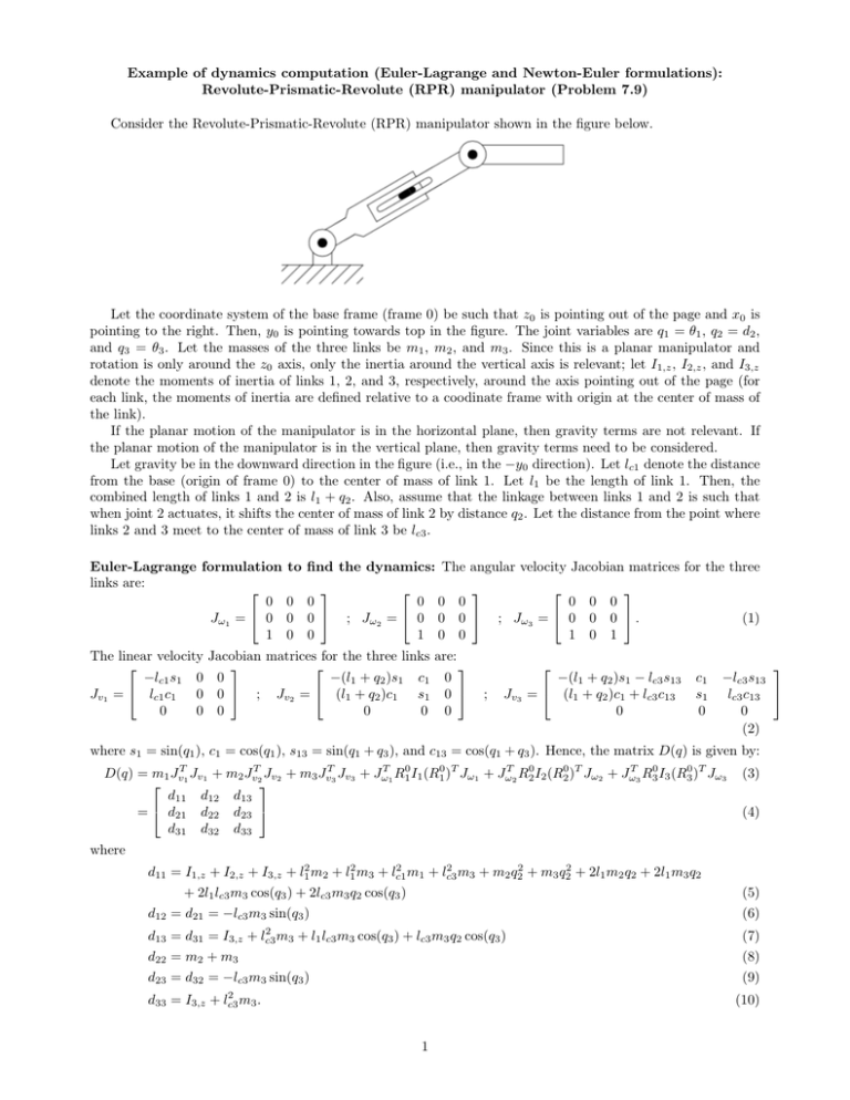
Consider the Revolute-Prismatic-Revolute (RPR) manipulator shown in the figure below.
Let the coordinate system of the base frame (frame 0) be such that z0 is pointing out of the page and x0 is
pointing to the right. Then, y0 is pointing towards top in the figure. The joint variables are q1 = θ1 , q2 = d2 ,
and q3 = θ3 . Let the masses of the three links be m1 , m2 , and m3 . Since this is a planar manipulator and
rotation is only around the z0 axis, only the inertia around the vertical axis is relevant; let I1,z , I2,z , and I3,z
denote the moments of inertia of links 1, 2, and 3, respectively, around the axis pointing out of the page (for
each link, the moments of inertia are defined relative to a coodinate frame with origin at the center of mass of
the link).
If the planar motion of the manipulator is in the horizontal plane, then gravity terms are not relevant. If
the planar motion of the manipulator is in the vertical plane, then gravity terms need to be considered.
Let gravity be in the downward direction in the figure (i.e., in the −y0 direction). Let lc1 denote the distance
from the base (origin of frame 0) to the center of mass of link 1. Let l1 be the length of link 1. Then, the
combined length of links 1 and 2 is l1 + q2 . Also, assume that the linkage between links 1 and 2 is such that
when joint 2 actuates, it shifts the center of mass of link 2 by distance q2 . Let the distance from the point where
links 2 and 3 meet to the center of mass of link 3 be lc3 .
Euler-Lagrange formulation
links are:
0
Jω1 = 0
1
The linear velocity
−lc1 s1 0
Jv1 = lc1 c1 0
0
0
to find the dynamics: The angular velocity Jacobian matrices for the three
0
0
0
0
0
0
; Jω2
0
= 0
1
0
0
0
0
0
0
Jacobian matrices for the three links are:
0
−(l1 + q2 )s1 c1 0
0 ; Jv2 = (l1 + q2 )c1 s1 0
0
0
0 0
; Jω3
0
= 0
1
;
J v3
0
0
0
0
0 .
1
−(l1 + q2 )s1 − lc3 s13
= (l1 + q2 )c1 + lc3 c13
0
(1)
c1
s1
0
−lc3 s13
lc3 c13
0
(2)
where s1 = sin(q1 ), c1 = cos(q1 ), s13 = sin(q1 + q3 ), and c13 = cos(q1 + q3 ). Hence, the matrix D(q) is given by:
D(q) = m1 JvT1 Jv1 + m2 JvT2 Jv2 + m3 JvT3 Jv3 + JωT1 R10 I1 (R10 )T Jω1 + JωT2 R20 I2 (R20 )T Jω2 + JωT3 R30 I3 (R30 )T Jω3
d11 d12 d13
= d21 d22 d23
d31 d32 d33
(3)
(4)
where
2
2
d11 = I1,z + I2,z + I3,z + l12 m2 + l12 m3 + lc1
m1 + lc3
m3 + m2 q22 + m3 q22 + 2l1 m2 q2 + 2l1 m3 q2
+ 2l1 lc3 m3 cos(q3 ) + 2lc3 m3 q2 cos(q3 )
(5)
d12 = d21 = −lc3 m3 sin(q3 )
d13 = d31 = I3,z +
2
lc3
m3
(6)
+ l1 lc3 m3 cos(q3 ) + lc3 m3 q2 cos(q3 )
(7)
d22 = m2 + m3
(8)
d23 = d32 = −lc3 m3 sin(q3 )
(9)
2
d33 = I3,z + lc3
m3 .
(10)
1
As described above, since the rotation of all the links is
about the axis pointing out of the page are relevant (i.e.,
Finding the Christoffel symbols cijk as
1 ∂dkj
cijk =
+
2 ∂qi
only about the z0 axis, only the moments of inertia
I1,z , I2,z , I3,z ).
∂dki
∂dij
−
∂qj
∂qk
for i = 1, 2, 3; j = 1, 2, 3; k = 1, 2, 3, and writing the matrix C(q, q̇) with its its (k, j)th element being
n
X
ckj =
cijk (q)q̇i ,
(11)
(12)
i=1
we get
C11 (q, q̇) C12 (q, q̇) C13 (q, q̇)
C(q, q̇) = C21 (q, q̇) C22 (q, q̇) C23 (q, q̇)
C31 (q, q̇) C32 (q, q̇) C33 (q, q̇)
(13)
C11 (q, q̇) = q̇2 (l1 m2 + l1 m3 + m2 q2 + m3 q2 + lc3 m3 cos(q3 )) − lc3 m3 q̇3 sin(q3 )(l1 + q2 )
(14)
C12 (q, q̇) = q̇1 (l1 m2 + l1 m3 + m2 q2 + m3 q2 + lc3 m3 cos(q3 ))
(15)
where
C13 (q, q̇) = −lc3 m3 sin(q3 )(l1 + q2 )(q̇1 + q̇3 )
(16)
C21 (q, q̇) = −q̇1 (l1 m2 + l1 m3 + m2 q2 + m3 q2 + lc3 m3 cos(q3 )) − lc3 m3 q̇3 cos(q3 )
(17)
C22 (q, q̇) = 0
(18)
C23 (q, q̇) = −lc3 m3 cos(q3 )(q̇1 + q̇3 )
(19)
C31 (q, q̇) = lc3 m3 q̇2 cos(q3 ) + lc3 m3 q̇1 sin(q3 )(l1 + q2 )
(20)
C32 (q, q̇) = lc3 m3 q̇1 cos(q3 )
(21)
C33 (q, q̇) = 0
(22)
The potential energy of the manipulator is given by:
P = m1 glc1 sin(q1 ) + m2 g(l1 + q2 ) sin(q1 ) + m3 g(sin(q1 )(l1 + q2 ) + lc3 sin(q1 + q3 )).
(23)
Hence,
g(q) =
∂P
∂q1
∂P
∂q2
∂P
∂q3
m1 glc1 cos(q1 ) + m2 g(l1 + q2 ) cos(q1 ) + m3 g(cos(q1 )(l1 + q2 ) + lc3 cos(q1 + q3 ))
.
m2 g sin(q1 ) + m3 g sin(q1 )
=
m3 glc3 cos(q1 + q3 )
(24)
The dynamical equations of the manipulator are given by:
q̈1
τ1
D(q) q̈2 + C(q, q̇)q̇ + g(q) = f2
q̈3
τ3
(25)
where τ1 is the applied torque at the first joint (revolute), f2 is the applied force at the second joint (prismatic),
and τ3 is the applied torque at the third joint (revolute).
Newton-Euler formulation to find the dynamics:
• Forward recursion: To assign the Denavit-Hartenberg coordinate frames, pick z0 pointing out of the page
and x0 to the right in the figure (i.e., y0 pointing towards top in the figure); pick z1 pointing along the
actuation axis of the second joint; x1 should be picked such that it intersects both z0 and z1 and is
perpendicular to both z0 and z1 . Hence, x1 is in the plane of the page and the origins of frames 0 and 1
are at the same location. Then, y1 can point out of the page. Pick z2 pointing out of the page (rotation
axis of the third joint). x2 has to be picked such that it intersects both z1 and z2 and is perpendicular
to both z1 and z2 . Hence, x2 is in the plane of the page. y2 is also in the plane of the page. y2 is in the
same direction as −z1 . Pick z3 parallel to z2 (with origin of frame 3 at the end-effector). Then, x3 can be
picked in the plane of the page pointing forward from the end-effector. The Denavit-Hartenberg table for
this manipulator is:
2
Link
1
2
3
ai
0
0
l3
αi
90o
-90o
0
di
0
l1 + q2
0
θi
90o + q1
0
-90o + q3
We have
−s1
R10 = c1
0
0 c1
1
0 s1 ; R21 = 0
1 0
0
0
0
−1
0
s3
1 ; R32 = −c3
0
0
c3
s3
0
0
0 .
1
(26)
The angular velocities of the links (written relative to the link-fixed frames) are ω1 = q̇1~j, ω2 = q̇1~k, and
ω3 = (q̇1 + q̇3 )~k. Here, the notations ~i, ~j, and ~k denote the 3×1 unit vectors, i.e., ~i = [1, 0, 0]T , ~j = [0, 1, 0]T ,
~k = [0, 0, 1]T . The gravity vector can be written in the link-fixed frames as: g1 = g[−c1 , 0, −s1 ]T ,
g2 = g[−c1 , s1 , 0]T , and g3 = g[−s13 , −c13 , 0]T .
Since the base frame is stationary, we have ac,0 = ae,0 = 0. Looking at the orientation of frame 1, we have
r1,c1 = lc1~k. Hence, the linear acceleration of the center of mass of link 1 is:
ac,1 = R01 ae,0 + ω̇1 × r1,c1 + ω1 × (ω1 × r1,c1 ) = lc1 q̈1~i − lc1 q̇12~k.
(27)
Since the origins of frames 0 and 1 are at the same point, it is convenient to take the end of link 1 to be at
the origin of frames 0 and 1. Note that the end of the link can be defined to be at any convenient location
fixed to the link as long as we keep the equations consistent. If we pick the end of link 1 to be at the fixed
base (origin of frames 0 and 1), then ae,1 = 0. We can write r2,c2 = −(l1 + q2 )~j. Also, r2,c1 = r1,c1 . The
(0)
linear acceleration ac,2 = R02 v̇c,2 of the center of mass of link 2 can be found to be:
ac,2 = (q̈1 (l1 + q2 ) + 2q̇1 q̇2 )~i + ((l1 + q2 )q̇12 − q̈2 )~j. Also, by the assumption mentioned near the top of page
that the linkage between links 1 and 2 is such that when joint 2 actuates, it shifts the center of mass of
link 2 by distance q2 , we can write ae,2 = ac,2 . Note that r3,c3 = lc3~i and r3,c2 = [0, 0, 0]T . We can write
ac,3 = (c3 ((−l1 − q2 )q̇12 + q̈2 ) − lc3 (q̇1 + q̇3 )2 + s3 (q̈1 (l1 + q2 ) + 2q̇1 q̇2 ))~i
+ (lc3 (q̈1 + q̈3 ) − s3 ((−l1 − q2 )q̇12 + q̈2 ) + c3 (q̈1 (l1 + q2 ) + 2q̇1 q̇2 ))~j.
(28)
• Backward recursion: Start with f4 = τ4 = 0. Then,
f3 = m3 (ac,3 − g3 ) = f3,x~i + f3,y~j
(29)
τ3 = −f3 × r3,c3 + I3 ω̇3 + ω3 × (I3 ω3 ) = τ3,z~k
(30)
where
f3,x = m3 (c3 ((−l1 − q2 )q̇12 + q̈2 ) − lc3 (q̇1 + q̇3 )2 + gs13 + s3 (q̈1 (l1 + q2 ) + 2q̇1 q̇2 ))
f3,y = m3 (lc3 (q̈1 + q̈3 ) + gc13 − s3 ((−l1 −
q2 )q̇12
(31)
+ q̈2 ) + c3 (q̈1 (l1 + q2 ) + 2q̇1 q̇2 ))
τ3,z = I3,z (q̈1 + q̈3 ) + lc3 m3 (lc3 (q̈1 + q̈3 ) + gc13 − s3 ((−l1 −
q2 )q̇12
(32)
+ q̈2 ) + c3 (q̈1 (l1 + q2 ) + 2q̇1 q̇2 )). (33)
Then,
f2 = R32 f3 + m2 (ac,2 − g2 ) = f2.x~i + f2.y~j
(34)
τ2 = R32 τ3 − f2 × r2,c2 + (R32 f3 ) × r3,c2 + I2 ω̇2 + ω2 × (I2 ω2 ) = τ2,z~k
(35)
where
f2,x = g(m2 + m3 )c1 + l1 (m2 + m3 )q̈1 + (m2 + m3 )q2 q̈1 + 2(m2 + m3 )q̇1 q̇2 + lc3 m3 (q̈1 + q̈3 )c3
− lc3 m3 (q̇12 + q̇32 )s3 − 2lc3 m3 q̇1 q̇3 s3
f2,y =
l1 m2 q̇12
+
− (m2 + m3 )q̈2 +
lc3 m3 (q̇12
+
q̇32 )c3
l1 m3 q̇12
(36)
+ (m2 +
m3 )q2 q̇12
+ 2lc3 m3 q̇1 q̇3 c3
(37)
τ2,z = I2,z q̈1 + (l1 + q2 )(m2 (ã1 + gc1 ) + m3 s3 (c3 ((−l1 −
+
+
− g(m2 + m3 )s1 + lc3 m3 (q̈1 + q̈3 )s3
q2 )q̇12
+ q̈2 ) − lc3 (q̇1 + q̇3 ) + gs13 + s3 ã1 )
m3 c3 (lc3 (q̈1 + q̈3 ) + gc13 − s3 ((−l1 − q2 )q̇12 + q̈2 ) + c3 ã1 ))
lc3 m3 (lc3 (q̈1 + q̈3 ) + gc13 − s3 ((−l1 − q2 )q̇12 + q̈2 ) + c3 ã1 )
3
2
+ I3,z (q̈1 + q̈3 )
(38)
where ã1 = (q̈1 (l1 + q2 ) + 2q̇1 q̇2 ). Then,
f1 = R21 f2 + m1 (ac,1 − g1 ) = f1,x~i + f1,z~k
(39)
τ1 = R21 τ2 − f1 × r1,c1 + (R21 f2 ) × r2,c1 + I1 ω̇1 + ω1 × (I1 ω1 ) = τ1,y~j
(40)
where
f1,x = g(m1 + m2 + m3 )c1 + l1 (m2 + m3 )q̈1 + lc1 m1 q̈1 + (m2 + m3 )q2 q̈1 + 2m2 q̇1 q̇2 + 2m3 q̇1 q̇2
+ lc3 m3 (q̈1 + q̈3 )c3 − lc3 m3 (q̇12 + q̇32 )s3 − 2lc3 m3 q̇1 q̇3 s3
(41)
f1,z = (m2 + m3 )q̈2 − l1 (m2 + m3 )q̇12 − lc1 m1 q̇12 − (m2 + m3 )q2 q̇12 + g(m1 + m2 + m3 )s1
− lc3 m3 (q̈1 + q̈3 )s3 − lc3 m3 (q̇12 + q̇32 )c3 − 2lc3 m3 q̇1 q̇3 c3
τ1,y = (I1,z + I2,z + I3,z )q̈1 + I3,z q̈3 + (m2 + m3 ){l12 q̈1 + q22 q̈1 + 2l1 q2 q̈1 + 2l1 q̇1 q̇2 + 2q2 q̇1 q̇2 +
2
2
+ lc1
m1 q̈1 + lc3
m3 (q̈1 + q̈3 ) + glc3 m3 c13 + glc1 m1 c1 − lc3 m3 q̈2 s3 − (l1 + q2 )lc3 m3 q̇32 s3
(42)
gl1 c1 + gq2 c1 }
+ l1 lc3 m3 (2q̈1 + q̈3 )c3 + lc3 m3 q2 (2q̈1 + q̈3 )c3 + 2lc3 m3 q̇1 q̇2 c3 − 2(l1 + q2 )lc3 m3 q̇1 q̇3 s3
(43)
Since the actuation of the first joint is along z0 = y1 , the actuated joint torque for the first joint (revolute)
is τ1,y . Since the actuation of the second joint is along z1 = −y2 , the actuated joint force for the second
joint is −f2,y . Since the actuation of the third joint is along z2 = z3 , the actuated joint torque for the third
joint is τ3,z . Another way to see which joint forces/torques are the externally actuated forces/torques is
(i)
(i)
(i)
to look at fiT zi−1 or τiT zi−1 (depending on whether joint i is prismatic or revolute) where zi−1 denotes
(1)
(2)
(3)
the axis zi−1 written relative to frame i; here, τ1T z0 = τ1,y , f2T z1 = −f2,y , and τ3T z2 = τ3,z .
Therefore, the dynamics equations are:
u1 = (I1,z + I2,z + I3,z )q̈1 + I3,z q̈3 + (m2 + m3 ){l12 q̈1 + q22 q̈1 + 2l1 q2 q̈1 + 2l1 q̇1 q̇2 + 2q2 q̇1 q̇2 + gl1 c1 + gq2 c1 }
2
2
+ lc1
m1 q̈1 + lc3
m3 (q̈1 + q̈3 ) + glc3 m3 c13 + glc1 m1 c1 − lc3 m3 q̈2 s3 − (l1 + q2 )lc3 m3 q̇32 s3
+ l1 lc3 m3 (2q̈1 + q̈3 )c3 + lc3 m3 q2 (2q̈1 + q̈3 )c3 + 2lc3 m3 q̇1 q̇2 c3 − 2(l1 + q2 )lc3 m3 q̇1 q̇3 s3
u2 = − l1 m2 q̇12 − (m2 + m3 )q̈2 + l1 m3 q̇12 + (m2 + m3 )q2 q̇12 − g(m2 + m3 )s1 + lc3 m3 (q̈1 + q̈3 )s3
+ lc3 m3 (q̇12 + q̇32 )c3 + 2lc3 m3 q̇1 q̇3 c3
u3 = I3,z (q̈1 + q̈3 ) + lc3 m3 (lc3 (q̈1 + q̈3 ) + gc13 − s3 ((−l1 −
q2 )q̇12
+ q̈2 ) + c3 (q̈1 (l1 + q2 ) + 2q̇1 q̇2 ))
(44)
(45)
(46)
where u1 is the actuated torque for the first joint, u2 is the actuated force for the second joint, and u3 is
the actuated torque for the third joint.
4
