B751e, Outdoor Disconnectors, Earthing Switches
advertisement

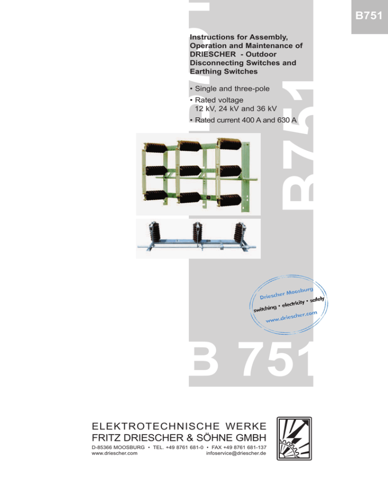
B75 B751 • Single and three-pole B751 Instructions for Assembly, Operation and Maintenance of DRIESCHER - Outdoor Disconnecting Switches and Earthing Switches • Rated voltage 12 kV, 24 kV and 36 kV • Rated current 400 A and 630 A B 751 ELEKTROTECHNISCHE WERKE FRITZ DRIESCHER & SÖHNE GMBH D-85366 MOOSBURG • TEL. +49 8761 681-0 • FAX +49 8761 681-137 www.driescher.com infoservice@driescher.de B751 Transport and storage Once you have received the delivery please carefully unpack the switching devices and check for any transportation damage. Should you determine any damage please report this immediately and indicate the carrier. After unpacking, clean the switching devices and accessories to remove any contamination from packing material and protect against moisture and contamination prior to installation. To transport the switching devices only hold at the frame and never touch the contact blades etc. Thoroughly clean the switches and actuator elements prior to putting into operation to remove dust and installation swarf and wipe all insulating parts with a clean dry cloth. Operating conditions The switches are designed for normal operating conditions in compliance EN 62271-1 Class "Minus 25 Outdoor". The max. ambient temperature is 40°C; the average value over 24 hours is max. 35°C. The values on insulation strength are related to sea level. For altitudes of up to 1000 m any reduction in insulation caused by the reduced insulating property of the air is insignificant and can be ignored. For installation at altitudes above 1000 m it is necessary to correct the values given for the rated powerfrequency withstand voltage and the rated lightning impulse withstand voltage. According to EN 62271-1 the insulating property of the clearance at an altitude of e.g. 2000 m is reduced by the factor 0.81. Assembly Unless otherwise specified the switches are designed for vertical frame or wall mounting. Switches for horizontal installation or for mounting on roofs are appropriately adjusted and marked. For the assembly of the earthing and disconnecting switches always observe the following: - If using circular conductors with conical terminals the clamping cones must be tightened prior to connections with the connecting contacts. - Make sure not to distort the base frame of the switch when tightening the fixing screws. When touching up any damaged paint surfaces, always make sure not to apply paint to bearings and joints, springs and plastic parts or parts with galvanized protective coating. - Do not fasten wall-mounting switching devices directly to the wall as its surface is usually uneven. We recommend mounting the switches on accurately aligned cross arms set up in front of the wall or to accurately adjust the switching devices on four ragbolts inserted in the wall, using two lock nuts respectively. - Hold the fixing screws in place with a second wrench when tightening the nuts. When switching on and off in wall-mounted switching devices, the applied operating mechanism must reach the stop position without causing any overtravel in the operating mechanism. Observe direction of rotation! (refer to 774 and 776) - When connecting cables and rails make sure to avoid any tension, thrust or torsion at the connecting contacts. Commissioning and operation The operation or ON and OFF switching of the disconnecting switch and earthing switch is by means of an operating mechanism which can be optionally installed to the right or to the left of the operating shafts (Fig. 3 , 12 ). For instructions on the actuation of all operating mechanisms please refer to 774 (Actuators) and 776 (Motor-Operated Mechanisms). Installed adjustable auxiliary switches signal when the end positions of the earthing switch are attained. 2 The switching instant has already been correctly adjusted prior to delivery. Each and every switch is adjusted and tested prior to leaving the factory! Nevertheless, satisfactory operation of the switch should be checked prior to commissioning. When doing this, please observe the following points: B751 Commissioning and operation 1. The stops of the operating shafts ( 4 , 11 ) must reach their end position. The switching angle for disconnecting and earthing switches is 90°. 2. The functional check of the electromagnetic interlocking between earthing switch and associated switch is mandatory. This should be carried out in deenergized condition. 3. The main circuits 5 and 10 of the switching devices must strike exactly in the provided contact jaws 2 and 9 . 4. Check satisfactory operation of mounted signalling contacts. • • • •• • Note: In switchgears with electromagnet interlocking the switch can only be operated when voltage is applied to the interlocking electromagnet. In de-energized condition the electromagnet locks the switch. The operating shaft of the associated switch is arrested by an interlocking device which is operated by an electromagnetically operated mechanism, type Hahn GL 90. In the control voltage there is a permissible tolerance of 15% of the rated voltage of the magnet. 1 Upper connection 2 Contact jaw 3 Actuator shaft 4 Stop of operating shaft 5 Main circuit 6 Pivot contact 7 Lower connection 8 Connection • Fig. 1: Outdoor disconnecting switch • • • • Fig. 2: Outdoor earthing switch • 9 Contact jaw 10 Main circuit 11 Stop of operating shaft 12 Actuator shaft 4 , 11 Side view Note: In order to be able to guarantee the satisfactory operation of the disconnecting and earthing switch we kindly ask you to contact our trained staff for adjustments or subsequent attachment of accessories. 3 B751 Inspection • Maintenance • Repair General Maintenance (refer to Fig. 1 and 2) Our products have been on the market for many years and hundreds of thousands of these switching devices are used successfully. We are able to say that the quality of our products is distinguished by a high level of ruggedness and operational safety and reliability. To guarantee that the requirements put to the switching devices are met and to avoid any possible power failures, appropriate maintenance, inspection and possible repair measures are necessary to provide a reliable power supply, wherein the measures taken depend on the age of the switching devices, its switching frequency and the level of the operated rated current. a) Clean contacts ( 2 , 9 ) with a solvent or degreasing agent (e.g. industrial alcolhol). b) Apply a thin film of contact grease, L55/1 of Klüber/Lubrikation. c) Check all bearings and joints for ease of movement and lubricate with Rivolta S.K.D. 16 of Bremer & Leguil. d) Clean the insulators. e) Check the switch for correct switching action by carrying out several trail switching operations. Repair Inspection Inspection should be carried out on disconnecting and earthing switches after approx. 10 years of operation in addition to annual visual checks, even if the switch is only operated with small loads and not very often. Shorter intervals between inspections may be necessary in the event of: negative impact from the environment, such as: • corrosive atmospheres, air with a high dust content, damp plant facilities etc. • high switching frequency Only mount and remove switch parts and accessories after disconnecting the switch and after isolating and safeguarding the working area in accordance with VBG 4 regulations. Disassembly as well as removal and installation of the switch (parts) are only to be carried out by DRIESCHER personnel or appropriately authorized skilled personnel, this being due in particular to the expertise required for the correct adjustment. Service You can reach our trained personnel at any time, also outside office hours, under Tel. +49 87 61 6 81-0, for assistance in troubleshooting or information on compatibility, assembly or maintenance. Dimensions, weights, diagrams and descriptions in this brochure are non-binding. Subject to change without notice. switching • electricity • safely Printed on chlorine free bleached paper. For nature´s sake. ELEKTROTECHNISCHE WERKE FRITZ DRIESCHER & SÖHNE GMBH D-85366 MOOSBURG • TEL. +49 8761 681-0 • FAX +49 8761 681-137 www.driescher.com infoservice@driescher.de Order No. 3-81202051 • 08-03


