Blue Point Engineering LED Data
advertisement

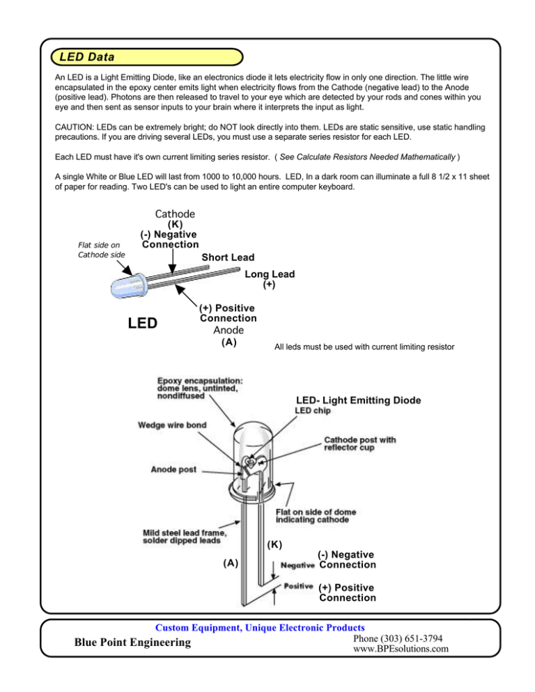
LED Data An LED is a Light Emitting Diode, like an electronics diode it lets electricity flow in only one direction. The little wire encapsulated in the epoxy center emits light when electricity flows from the Cathode (negative lead) to the Anode (positive lead). Photons are then released to travel to your eye which are detected by your rods and cones within you eye and then sent as sensor inputs to your brain where it interprets the input as light. CAUTION: LEDs can be extremely bright; do NOT look directly into them. LEDs are static sensitive, use static handling precautions. If you are driving several LEDs, you must use a separate series resistor for each LED. Each LED must have it's own current limiting series resistor. ( See Calculate Resistors Needed Mathematically ) A single White or Blue LED will last from 1000 to 10,000 hours. LED, In a dark room can illuminate a full 8 1/2 x 11 sheet of paper for reading. Two LED's can be used to light an entire computer keyboard. Flat side on Cathode side Cathode (K) (-) Negative Connection Short Lead Long Lead (+) LED (+) Positive Connection Anode (A) All leds must be used with current limiting resistor LED- Light Emitting Diode (K) (A) (-) Negative Connection (+) Positive Connection Custom Equipment, Unique Electronic Products Phone (303) 651-3794 Blue Point Engineering www.BPEsolutions.com Blue Point Engineering Instruction www.BPEsolutions.com Pointing the Way to Solutions! LED Information LED's Single LED Configuration LED 9 Vdc Battery + Resistor (R) Anode (A) + - Cathode (K) + R LED Circuit - A K Series LED Configuration LED 9 Vdc Battery Resistor + + Anode - Cathode LED + Anode - Cathode R + LED A LED K A LED K A Circuit +Anode - Cathode LED - I K Custom Equipment, Unique Electronic Products Phone (303) 651-3794 Blue Point Engineering www.BPEsolutions.com Parallel LED Configuration LED 9 Vdc Battery + Resistor - 1 Anode - Cathode LED + Resistor - 2 - + Anode - Cathode LED Resistor - 3 + Anode - Cathode + R Circuit R A + R A A R A A A Circuit K LED K LED K - K LED LED K LED K LED Power Switch Configuration LED 9 Vdc Battery + Resistor (R) Anode (A) + - Cathode (K) + Circuit R LED A K SPST On / Off Switch - SWITCH Custom Equipment, Unique Electronic Products Phone (303) 651-3794 Blue Point Engineering www.BPEsolutions.com Blue Point Engineering Inc. Instruction www.BPEsolutions.com LED Information LED White Blue Green Red Yellow Blue-Green Orange RGB Ultra Violet Voltage Drop Vf 3.3 Vdc 3.1 vdc 3.3 vdc 2.25 Vdc 1.9 Vdc 3.2 Vdc 2.3 Vdc 3.1 Vdc 3.6 Vdc Controller Foward Current mA 20 mA 20 mA 20 mA 20 mA 20 mA 20 mA 20 mA 30 mA 30 mA LED Intensity Level mcd 8000 mcd 6000 mcd 4000 mcd 8000 mcd 3000 mcd 2000 mcd 3000 mcd 800 mcd 1000 mcd Calculate Resistors Needed Mathematically To calculate resistance. Ohms law is V=IR. Solving for R yields R=V/I V is voltage in volts, I is current in amps, and R is resistance in Ohms. V is the difference between the supplied voltage and the required voltage. Since we're using milliamps instead of amps, we need a multiplication factor of 1000. Since we're using the difference in supplied voltage and required LED voltage we need to subtract. The formula becomes R = (9 volts - LED voltage required) / (current in milliamps) * 1000 Once you've calculated the resistance, you will use the closest resistor value you can find. Example: White LED = 3.3 Vf 30mA I Power Supply- 9Vdc 9Vdc - 3.3Vdc / 20mA x 1000 = 285 Resistor Needed = 330 Ohm 1/4 Watt ( Nearest Resistor Value (330) Orange/Orange/Brown/Gold ) Calculated resistance value = 285 Ohms Next standard 10% resistor = 330 Ohm Power dissipated in LED = 0.114 Watts Power dissipated in resistor = 0.19 Watts LED Intensity The unit of measure commonly used to describe LED intensity is the millicandela (mcd). 1000mcd = 1cd. Candelas measure how much light is produced as measured at the light source in a specific direction. Custom Equipment, Unique Electronic Products Phone (303) 651-3794 Blue Point Engineering Inc. www.BPEsolutions.com


