Chapter 23 Alternating Current Circuits
advertisement
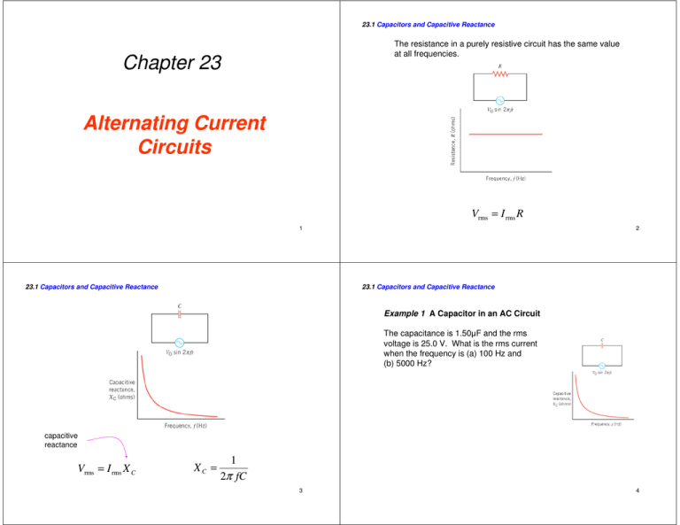
23.1 Capacitors and Capacitive Reactance The resistance in a purely resistive circuit has the same value at all frequencies. Chapter 23 Alternating Current Circuits Vrms = I rms R 1 23.1 Capacitors and Capacitive Reactance 2 23.1 Capacitors and Capacitive Reactance Example 1 A Capacitor in an AC Circuit The capacitance is 1.50µF and the rms voltage is 25.0 V. What is the rms current when the frequency is (a) 100 Hz and (b) 5000 Hz? capacitive reactance Vrms = I rms X C XC = 1 2π fC 3 4 23.1 Capacitors and Capacitive Reactance (a) (b) XC = 23.1 Capacitors and Capacitive Reactance 1 1 = = 1060Ω 2π fC 2π (100 Hz ) 1.50 ×10 −6 F ( ) I rms = Vrms 25.0 V = = 0.0236 A X C 1060Ω XC = 1 1 = = 21.2Ω 2π fC 2π (5000 Hz ) 1.50 ×10 −6 F I rms = ( For a purely resistive circuit, the current and voltage are in phase. ) Vrms 25.0 V = = 1.18 A X C 21.2Ω 5 23.1 Capacitors and Capacitive Reactance 6 23.1 Capacitors and Capacitive Reactance In the phasor model, the voltage and current are represented by rotating arrows (called phasors). The current in a capacitor leads the voltage across the capacitor by a phase angle of 90 degrees. These phasors rotate at a frequency f. The vertical component of the phasor is the instantaneous value of the current or voltage. The average power used by a capacitor in an ac circuit is zero. 7 8 23.2 Inductors and Inductive Reactance 23.2 Inductors and Inductive Reactance inductive reactance The current lags behind the voltage by a phase angle of 90 degrees. Vrms = I rms X L X L = 2π f L The average power used by an inductor in an ac circuit is zero. 9 23.2 Inductors and Inductive Reactance 10 23.3 Circuits Containing Resistance, Capacitance, and Inductance In a series RLC circuit, the total opposition to the flow is called the impedance. 2 Vrms = I rms Z 11 Z = R2 + (X L − X C ) 12 23.3 Circuits Containing Resistance, Capacitance, and Inductance 23.3 Circuits Containing Resistance, Capacitance, and Inductance phase angle between current and total voltage 2 Z = R2 + (X L − X C ) tan φ = VL − VC X L − X C = VR R 2 P = I rms Z cos φ = I rmsVrms cos φ 13 23.4 Resonance in Electric Circuits 14 23.4 Resonance in Electric Circuits Resonance occurs when the frequency of a vibrating force exactly matches a natural (resonant) frequency of the object to which the force is applied. I rms = The oscillation of a mass on a spring is analogous to the oscillation of the electric and magnetic fields that occur, respectively, in a capacitor and an inductor. Vrms 2 R + (2πfL − 1 2πfC ) 2 2 Z = R 2 + (2πfL − 1 2πfC ) Resonant frequency 15 fo = 1 2π LC 16 23.5 Semiconductor Devices 23.5 Semiconductor Devices n-TYPE AND p-TYPE SEMICONDUCTORS Semiconductor devices such as diodes and transistors are widely used in modern electronics. The semiconducting materials (silicon and germanium) used to make diodes and transistors are doped by adding small amounts of an impurity element. 17 23.5 Semiconductor Devices 18 23.5 Semiconductor Devices THE SEMICONDUCTOR DIODE At the junction between the n and p materials, mobile electrons and holes combine and create positive and negative charge layers. 19 20 23.5 Semiconductor Devices 23.5 Semiconductor Devices There is an appreciable current through the diode when the diode is forward biased. Under a reverse bias, there is almost no current through the diode. 21 23.5 Semiconductor Devices 22 23.5 Semiconductor Devices SOLAR CELLS A half-wave rectifier. 23 24 23.5 Semiconductor Devices 23.5 Semiconductor Devices TRANSISTORS A bipolar junction transistor can be used to amplify a smaller voltage into a larger one. 25 23.5 Semiconductor Devices 27 26
