4.2 Probe pulses Generated frequently Up to 30 pulses per second
advertisement
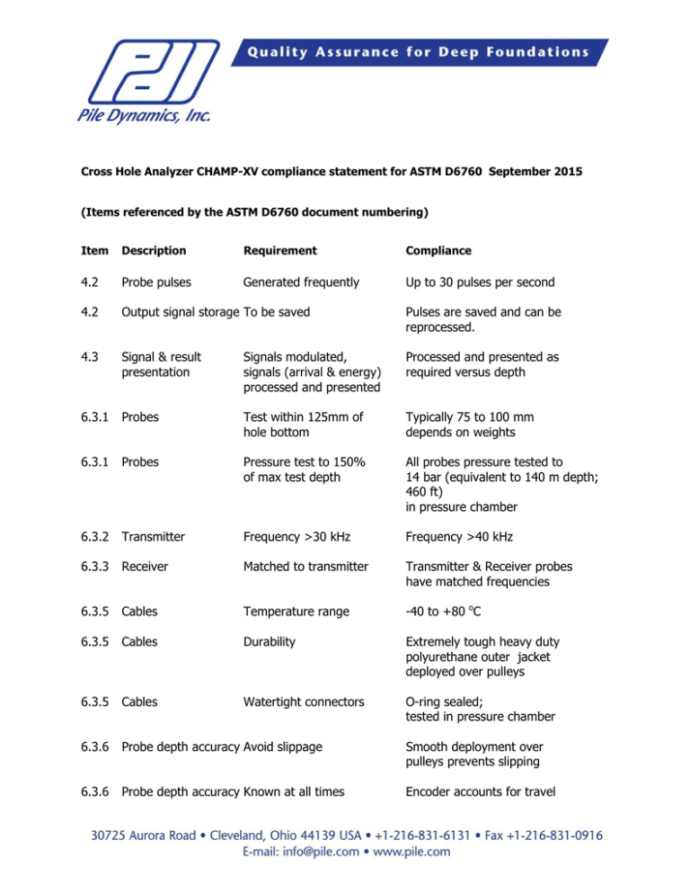
Cross Hole Analyzer CHAMP-XV compliance statement for ASTM D6760 September 2015 (Items referenced by the ASTM D6760 document numbering) Item Description Requirement Compliance 4.2 Probe pulses Generated frequently Up to 30 pulses per second 4.2 Output signal storage To be saved Pulses are saved and can be reprocessed. 4.3 Signal & result presentation Signals modulated, signals (arrival & energy) processed and presented Processed and presented as required versus depth 6.3.1 Probes Test within 125mm of hole bottom Typically 75 to 100 mm depends on weights 6.3.1 Probes Pressure test to 150% of max test depth All probes pressure tested to 14 bar (equivalent to 140 m depth; 460 ft) in pressure chamber 6.3.2 Transmitter Frequency >30 kHz Frequency >40 kHz 6.3.3 Receiver Matched to transmitter Transmitter & Receiver probes have matched frequencies 6.3.5 Cables Temperature range -40 to +80 oC 6.3.5 Cables Durability Extremely tough heavy duty polyurethane outer jacket deployed over pulleys 6.3.5 Cables Watertight connectors O-ring sealed; tested in pressure chamber 6.3.6 Probe depth accuracy Avoid slippage Smooth deployment over pulleys prevents slipping 6.3.6 Probe depth accuracy Known at all times Encoder accounts for travel in either up or down direction, position depth known at all times 6.3.6 Probe depth accuracy Within 1% Good practice and calibration adjustment results in accuracy within a 1% interval 6.4.1 General design Rugged High impact case Rugged electronic parts 6.4.1 Signal sampling By depth or time High frequency sampling; each sample noted with depth 6.4.1 Signal Gain Adjustable User selected and known 6.4.2 Recording Min 12 bit A/D resolution 12 bit A/D converter 6.4.2 Sampling frequency >250 KHz 500 to 2,000 KHz user selectable 6.4.2 Data storage Signals and information Stores raw signals; each depth with complete information 6.4.4 Data display Display raw signals Signals displayed for each selected depth, either during acquisition or reprocessing 6.4.4 Data display Display processed result Results displayed, during acquisition or reprocessing 7.4.4 Access Tubes Documentation Tube lengths and spacings are stored with data 7.5.3 Depth reference Zero values Depth can be zeroed at either top or bottom of tubes 7.5.5 Transmitter power Adjustable User selectable 7.5.5 Receiver gain Adjustable User selectable 7.5.6 Pulling speed Maximum rate At typical 30 Hz generation and 50 mm test depth sample can pull at up to 1.5 m/sec 7.5.6 Pulling speed No loss of data Missed data causes warning; User can lower probe again and repeat at slower pull rate to assure no missed samples 7.5.6 Probe levels (Note 4) Parallel or variable Two depth encoders allow independent measurement of probe depths 7.6 Single tube tests Applicability Can be used with both Probes in single access duct 7.7.1 Data quality Assurance User adjusted gain; adjustable data intensity view 7.9.1 Printed output Graphical Graphs vs. depth include first arrival time or wave speed, relative energy, “waterfall” 7.9.2 Printed output Numeric Automatically generated table for “defect analysis” from user arrival and energy input limits 7.9.3 Data smoothing Maximum limits Limited to max of 3 samples; If used, filter value printed


