Crosstalk Measurement Techniques for Multi
advertisement
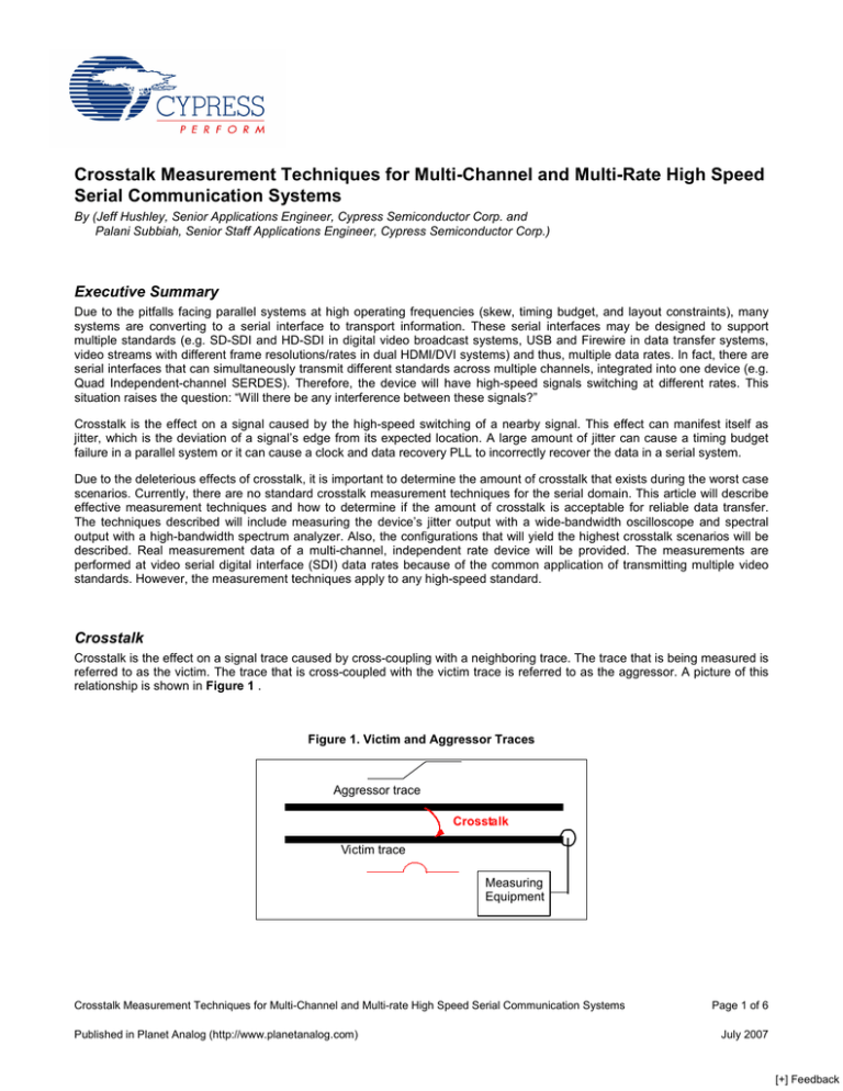
Crosstalk Measurement Techniques for Multi-Channel and Multi-Rate High Speed Serial Communication Systems By (Jeff Hushley, Senior Applications Engineer, Cypress Semiconductor Corp. and Palani Subbiah, Senior Staff Applications Engineer, Cypress Semiconductor Corp.) Executive Summary Due to the pitfalls facing parallel systems at high operating frequencies (skew, timing budget, and layout constraints), many systems are converting to a serial interface to transport information. These serial interfaces may be designed to support multiple standards (e.g. SD-SDI and HD-SDI in digital video broadcast systems, USB and Firewire in data transfer systems, video streams with different frame resolutions/rates in dual HDMI/DVI systems) and thus, multiple data rates. In fact, there are serial interfaces that can simultaneously transmit different standards across multiple channels, integrated into one device (e.g. Quad Independent-channel SERDES). Therefore, the device will have high-speed signals switching at different rates. This situation raises the question: “Will there be any interference between these signals?” Crosstalk is the effect on a signal caused by the high-speed switching of a nearby signal. This effect can manifest itself as jitter, which is the deviation of a signal’s edge from its expected location. A large amount of jitter can cause a timing budget failure in a parallel system or it can cause a clock and data recovery PLL to incorrectly recover the data in a serial system. Due to the deleterious effects of crosstalk, it is important to determine the amount of crosstalk that exists during the worst case scenarios. Currently, there are no standard crosstalk measurement techniques for the serial domain. This article will describe effective measurement techniques and how to determine if the amount of crosstalk is acceptable for reliable data transfer. The techniques described will include measuring the device’s jitter output with a wide-bandwidth oscilloscope and spectral output with a high-bandwidth spectrum analyzer. Also, the configurations that will yield the highest crosstalk scenarios will be described. Real measurement data of a multi-channel, independent rate device will be provided. The measurements are performed at video serial digital interface (SDI) data rates because of the common application of transmitting multiple video standards. However, the measurement techniques apply to any high-speed standard. Crosstalk Crosstalk is the effect on a signal trace caused by cross-coupling with a neighboring trace. The trace that is being measured is referred to as the victim. The trace that is cross-coupled with the victim trace is referred to as the aggressor. A picture of this relationship is shown in Figure 1 . Figure 1. Victim and Aggressor Traces Aggressor trace Crosstalk Victim trace Measuring Equipment Crosstalk Measurement Techniques for Multi-Channel and Multi-rate High Speed Serial Communication Systems Published in Planet Analog (http://www.planetanalog.com) Page 1 of 6 July 2007 [+] Feedback Crosstalk is dependent upon the edge rate of the aggressor signal; a faster edge induces more crosstalk. When the operating frequency of a transmitter is increased, the transmitter usually increases its edge rate to improve the signal noise margin. Therefore, to test the worst case the aggressor channels should switch at the highest frequency (See advanced crosstalk measurement section for more detailed ananlysis ). Jitter Crosstalk is a concern because it can be a major contributor to the amount of jitter present in a device. Simply stated, jitter is the deviation of an edge from its expected location. A large amount of jitter in a serial communications link may cause bit errors in the received serial bit stream. Phase-Locked Loops Within any serializer/deserializer (SERDES) device, there is a transmit PLL and a receive PLL. A quad independent channel SERDES has four transmit and receive pairs, where each pair has its own reference clock. A concern is that when adjacent PLL’s are switching at different frequencies, additional crosstalk may occur. This section will briefly describe the structure of the transmit PLL and the tests that will be performed to measure its performance. The receive PLL has similar frequency response characteristics and will be tested similarly. The transmit PLL is a clock multiplier unit (CMU). It receives an input clock (REFCLK) and outputs a bit clock that has ten times the frequency of REFCLK. A diagram of a transmit PLL is shown in Figure 2 . The amount of jitter that propagates through a PLL depends on where the jitter entered the PLL. If it enters via the REFCLK input, only low frequency components will pass through because the PLL acts like a low-pass filter. Low-frequency jitter has a smaller impact on receiver performance because a clock and data recovery (CDR) PLL will track the low-frequency jitter and correctly receive the data. However, if jitter is injected inside the loop (by crosstalk between PLLs, for example), the system acts like a high-pass filter. Therefore, crosstalk between the PLLs can be a cause of harmful, high-frequency jitter. To test the performance of the PLLs, three frequency variations between victim and aggressor REFCLKs will be performed: large frequency offsets (>100 MHz), small frequency offsets (< 1 MHz), and nearly identical frequencies (<1 kHz) from different sources. Figure 2. Transmit PLL Block Diagram SHIFTER REFCLK VCON PHASE UP FREQ DOWN FILTER DET VCO/10 VCO SERIAL DATA BIT CLOCK DIVIDE BY 10 Jitter and Crosstalk Measurement Techniques Measuring crosstalk can be performed in two ways: Jitter in the time domain and crosstalk in the frequency domain. Measuring Crosstalk in the Time Domain To measure jitter in the time domain, the eye diagram of the victim channel’s output can be observed on a wide-bandwidth oscilloscope. An eye diagram is formed by a superposition of waveforms. The phase of these waveforms with respect to one another is determined by the phase difference with the trigger signal. The amount of jitter will be obtained by analyzing the histogram formed at the eye crossing (shown in Figure 3). The eye crossing is the point at which the positive edge and negative edge intersect. When the waveform intersects the histogram window, a “hit” is recorded in the histogram. The histogram formed in Figure 3 resembles a Gaussian distribution. Crosstalk Measurement Techniques for Multi-Channel and Multi-rate High Speed Serial Communication Systems Published in Planet Analog (http://www.planetanalog.com) Page 2 of 6 July 2007 [+] Feedback Figure 3. Jitter Measurements at the Eye Crossing Peak-peak Jitter Histogram Window Histogram The two important values obtained from this measurement are the peak-to-peak jitter and the root mean square (RMS) value. The peak-to-peak jitter is the difference between the minimum and maximum time of hits in the histogram. This value is nondeterministic because of the nature of random jitter, but can provide helpful information if the test is performed for a long period of time. The RMS value (or standard deviation) converges to a stable value quickly. Assuming a Gaussian distribution, 12 it can be proven that the peak-to-peak jitter will be greater than fourteen times the RMS value less than once in 10 bit -12 periods. Therefore, to ensure a 10 bit error rate, the jitter tolerance of the receiver should be greater than 14 times the RMS value. When testing for crosstalk in the time domain, the data pattern can be any pattern (as opposed to specific periodic sequences mentioned in the frequency domain section). This way, the true jitter budget in a real-world system can be tested. To determine the effect of crosstalk in the time domain, measure the increase in jitter on the victim channel between no aggressors and with aggressors. The figure below shows an example of this measurement. In this example, the victim channel is transmitting a pseudo-random Built-In Self Test (BIST) sequence at 1485Mbps. The aggressor channel (when enabled) is transmitting the highest possible frequency signal, which for this device is a 1010 pattern at 1500Mbps . The RMS jitter (aka Standard Deviation) increased from ~13.5ps with no aggressors to ~14.2ps with aggressors. This translates to an -12 increase in total jitter of ~10ps when targeting a BER of 10 . Figure 4. Time Domain Comparison Between Aggressors Disabled (Left) and Aggressors Enabled (Right) Victim Channel with No Aggressors Enabled Victim Channel with Aggressors Enabled Crosstalk Measurement Techniques for Multi-Channel and Multi-rate High Speed Serial Communication Systems Published in Planet Analog (http://www.planetanalog.com) Page 3 of 6 July 2007 [+] Feedback Measuring Crosstalk in the Frequency Domain To measure crosstalk in the frequency domain, a high bandwidth spectrum analyzer can be used. The amplitude of the victim’s fundamental frequency can be compared with the amplitude of the aggressor’s fundamental frequency. The fundamental frequency of a signal is the lowest natural frequency and is also called the first harmonic. For example, a perfect square wave 20-MHz clock has a fundamental frequency of 20 MHz. Furthermore, it is composed of a sum of sinusoids at multiples (or harmonics) of the fundamental frequency. The most prevalent harmonics of a square wave are the odd harmonics. The first (20 MHz, in this example), third (60 MHz), and fifth (100 MHz) harmonics contribute to most of the shape of the square wave. Thus, if the crosstalk components are significantly smaller than the fifth harmonic, their impact will be negligible. When looking at the frequency response of a fairly random data pattern, the spectrum will not only have peaks at the odd harmonics. Instead, the energy will be more distributed across the frequency range. In this case, it will be difficult to see the effects of crosstalk because the spectral energy floor may be higher than the crosstalk energy. Therefore, when measuring crosstalk on serial data transmitters, the most effective pattern is a 1010 periodic pattern. This pattern will look like a square wave and thus, will have a low energy floor when not at the odd harmonics. Figure 5 shows the spectrum of a victim channel that is transmitting a 1111100000 pattern at 270Mbps (SD-SDI serial signalling rate) while the aggressor channel is transmitting a 1010101010 pattern at 1485Mbps (HD-SDI serial signalling rate). In this case, the victim channel is equivalently transmitting a 27MHz square wave (270Mbps / 10bits per cycle) and the aggressor is equivalently transmitting a 742.5MHz square wave (1485Mbps / 2bits per cycle). The top graph in Figure 5 shows the energy (in dB) vs. frequency from 0 to 800MHz. Every gridline on the energy axis represents 7dB. Since this a realworld signal, there are some even harmonics, but they all have < -50dB (0.3%) the energy of the fundamental. The bottom graph in Figure 5 is zoomed in on the 125-165MHz region to show the largest crosstalk peak in the victim channel. This peak th is at 148.5MHz, which is the character rate of the aggressor channel. The other peak is the 5 harmonic of the victim signal at 135MHz (5 * 27MHz). In this case, the affect of crosstalk is almost negligible because the largest crosstalk peak has ~ -28dB (4%) as much energy as the fifth harmonic. In the top graph in Figure 5, the aggressor’s serial data fundamental frequency (742.5MHz) can also be seen. It has approximately the same energy as the peak at 148.5MHz. All other crosstalk peaks at >1GHz are smaller. In the above example, it shows the effect of crosstalk from the aggressor’s character clock and from the aggressor’s serial data. Crosstalk from the aggressor’s character clock may be because the character clock traces are routed to close together. Crosstalk from the aggressor’s serial data may be because the serial I/Os are not isolated well enough or that the serial PCB traces are too close together. If there was crosstalk at the aggressor’s bit clock frequency(in this case, 1485MHz), then the PLLs may be interfering with each other. This information can help the board or chip designer narrow down the cause of the crosstalk. Figure 5. Spectral Plot of Victim Channel 5th harmonic Crosstalk Crosstalk Measurement Techniques for Multi-Channel and Multi-rate High Speed Serial Communication Systems Published in Planet Analog (http://www.planetanalog.com) Page 4 of 6 July 2007 [+] Feedback Crosstalk Measurement Equipment Setup Figure 6 shows an example of a crosstalk measurement equipment setup for a multi-channel high-speed serial transmission device, which in this case is a Cypress CYV15G0404DXB Independent Channel Serializer/Deserializer. The reference character clock for each channel (REFCLKx) will be supplied by a different Agilent 8133A Pulse Generator. The RMS jitter from the pulse generator should be low because its jitter directly relates to the jitter of the serial outputs. Therefore, minimizing the reference clock jitter will make it easier to see the effect of crosstalk on the serial data path. The Agilent 8133A’s RMS jitter is less than 5 ps (1 ps typical). The measurements performed on the transmit side will be taken at the serial output OUTA+. The other channels can operate at independent data rates. The time-domain jitter measurement would be performed with an Agilent 86100A Wide-Bandwidth Oscilloscope. The frequency-domain measurement would be performed with an Agilent E4407B Spectrum Analyzer. The screenshot in Error! Reference source not found. is from the oscilloscope and the screenshot in Figure 5 is from the spectrum analyzer. To determine the worst case amount of crosstalk, all channels should be enabled and the transmitted signal should be looped back into the receiver to maximize the amout of crosstalk. When debugging the cause of the crosstalk, the approach may be to enable one channel at a time and observe the configuration that causes the largest increase in jitter or causes the highest energy peak at a frequency related to the aggressor channel. Figure 6. Crosstalk Measurement Equipment Setup Example Agilent 8133 Pulse Generator 8133A Cypress CYV15G0404DXB Quad Independent Channel SERDES Evaluation Board 3 GHz Puls e Ge ne ra tor FLASE / DAT A ME MOR Y TRI GGE R FLASE Agilent 86100 Oscilloscope SETTING 861 00A infiniium DCA W ide-Bandwidth Os cillosc ope Smp Single Run Clear D is play Hori zontal EXTERN AL IN PU T O CHAN NEL 2 OU TPUT CHAN NEL 1 OU TPUT OU TPUT OU TPUT Default Setup OU TPUT Cal I OUT Aut o Scale Local 1 Eye/Mask Mode 2 3 Agilent 83494A SELECT REFCLK B Os cillos cope Mode B Op ti cal TRI GGE R OUTPU T T rigger Level + IN Puls e Generator FLASE / DAT A Cl oc k Auxili ary Outputs In put 3 GHz ME MOR Y Vertica l Data Quick Meas ure M ar kers Source 8133A 4 86106A SIN GLE MODE CLOC K R EC OVER Y MOD ULE TDR/TDT Mode Free R un Front Panel Left M odule R ight Modul e P robe Power 10mW Max Opt ic al + _ 2V Max D C 50 Ω + _ 2V Max _ FLASE SETTING EXTERN AL IN PU T O CHAN NEL 2 OU TPUT CHAN NEL 1 OU TPUT OU TPUT OU TPUT OU TPUT I OUT REFCLK A 8133A A IN 3 GHz Puls e Generator FLASE / DAT A ME MOR Y TRI GGE R Agilent E4407 Spectrum Analyzer FLASE E4407B ESA -E SE RIES SPEC TR UM ANA LY ZER SETTING CONTROL F REQUENCY Channel O CHAN NEL 2 OU TPUT SYSTEM In Out / Output MODE A MPLITUDE Y S cale Display BW / A vg Tr ig Save MEA S URE Menu Se tup Sing e l Sw eep Ma rker Restar t Menu Co ntr ol Sour ce Mod e Setup Syst em Freq Coun t Pr eset Fil e S PA N X Sca e l Ω EXTERN AL IN PU T Pr n it Se tup Coup e l Pr n it CHAN NEL 1 OU TPUT OU TPUT OU TPUT OU TPUT I Peak Se ar ch MARKE R OUT REFCLKD 8 9 4 5 6 1 2 3 0 . +/- Rx Sp On Help D Next W ind ow Zo o m IF IN PU T RF OUT 50 Ω 9 kH z - 3GHz 50 VDC MA X R EV PW R 8133A 7 Marker LO OUTP UT INPUT 50 Ω Ent er PR OBE POWER EXT KEY BOARD V OLUME TE RM 1M 50 Ω IN 3 GHz Puls e Generator FLASE / DAT A ME MOR Y TRI GGE R FLASE SETTING EXTERN AL IN PU T O CHAN NEL 2 OU TPUT CHAN NEL 1 OU TPUT OU TPUT OU TPUT OU TPUT I OUT REFCLKC C IN Conclusion Using the time-domain measurement methodology, we can get a better idea of how crosstalk is impacting the performance of the system. Since jitter is the cause of bit errors, this measurement will help to determine the jitter budget of the system. Also, the data pattern can be any normal data pattern (e.g. PRBS 23), which enables real-world system analysis. The frequency-domain measurement methodology is a useful tool for determining the cause of the crosstalk. The spectrum analyzer screenshots provide an easy way of detecting peaks that are not part of the original signal. The frequency of those peaks can be used to determine which aggressor signals are causing the largest impact on the system and to determine where (PLL, signal traces, I/O buffers, etc.) the crosstalk is occurring. Crosstalk Measurement Techniques for Multi-Channel and Multi-rate High Speed Serial Communication Systems Published in Planet Analog (http://www.planetanalog.com) Page 5 of 6 July 2007 [+] Feedback References HOTLink™ Jitter Characteristics. Cypress Semiconductor application note. March 11, 1999. <http://www.cypress.com/ cfuploads/support/app_notes/jitter.pdf> Measuring Crosstalk in LVDS Systems. Cole, Elliot. Texas Instruments. January 2000. <http://focus.ti.com/lit/an/ slla064/slla064.pdf> Cypress Semiconductor 198 Champion Court San Jose, CA 95134-1709 Phone: 408-943-2600 Fax: 408-943-4730 http://www.cypress.com © Cypress Semiconductor Corporation, 2007. The information contained herein is subject to change without notice. Cypress Semiconductor Corporation assumes no responsibility for the use of any circuitry other than circuitry embodied in a Cypress product. Nor does it convey or imply any license under patent or other rights. Cypress products are not warranted nor intended to be used for medical, life support, life saving, critical control or safety applications, unless pursuant to an express written agreement with Cypress. Furthermore, Cypress does not authorize its products for use as critical components in life-support systems where a malfunction or failure may reasonably be expected to result in significant injury to the user. The inclusion of Cypress products in life-support systems application implies that the manufacturer assumes all risk of such use and in doing so indemnifies Cypress against all charges. PSoC Designer™, Programmable System-on-Chip™, and PSoC Express™ are trademarks and PSoC® is a registered trademark of Cypress Semiconductor Corp. All other trademarks or registered trademarks referenced herein are property of the respective corporations. This Source Code (software and/or firmware) is owned by Cypress Semiconductor Corporation (Cypress) and is protected by and subject to worldwide patent protection (United States and foreign), United States copyright laws and international treaty provisions. Cypress hereby grants to licensee a personal, non-exclusive, non-transferable license to copy, use, modify, create derivative works of, and compile the Cypress Source Code and derivative works for the sole purpose of creating custom software and or firmware in support of licensee product to be used only in conjunction with a Cypress integrated circuit as specified in the applicable agreement. Any reproduction, modification, translation, compilation, or representation of this Source Code except as specified above is prohibited without the express written permission of Cypress. Disclaimer: CYPRESS MAKES NO WARRANTY OF ANY KIND, EXPRESS OR IMPLIED, WITH REGARD TO THIS MATERIAL, INCLUDING, BUT NOT LIMITED TO, THE IMPLIED WARRANTIES OF MERCHANTABILITY AND FITNESS FOR A PARTICULAR PURPOSE. Cypress reserves the right to make changes without further notice to the materials described herein. Cypress does not assume any liability arising out of the application or use of any product or circuit described herein. Cypress does not authorize its products for use as critical components in life-support systems where a malfunction or failure may reasonably be expected to result in significant injury to the user. The inclusion of Cypress’ product in a life-support systems application implies that the manufacturer assumes all risk of such use and in doing so indemnifies Cypress against all charges. Use may be limited by and subject to the applicable Cypress software license agreement. Crosstalk Measurement Techniques for Multi-Channel and Multi-rate High Speed Serial Communication Systems Published in Planet Analog (http://www.planetanalog.com) Page 6 of 6 July 2007 [+] Feedback

