Importance of X10 Probes
advertisement

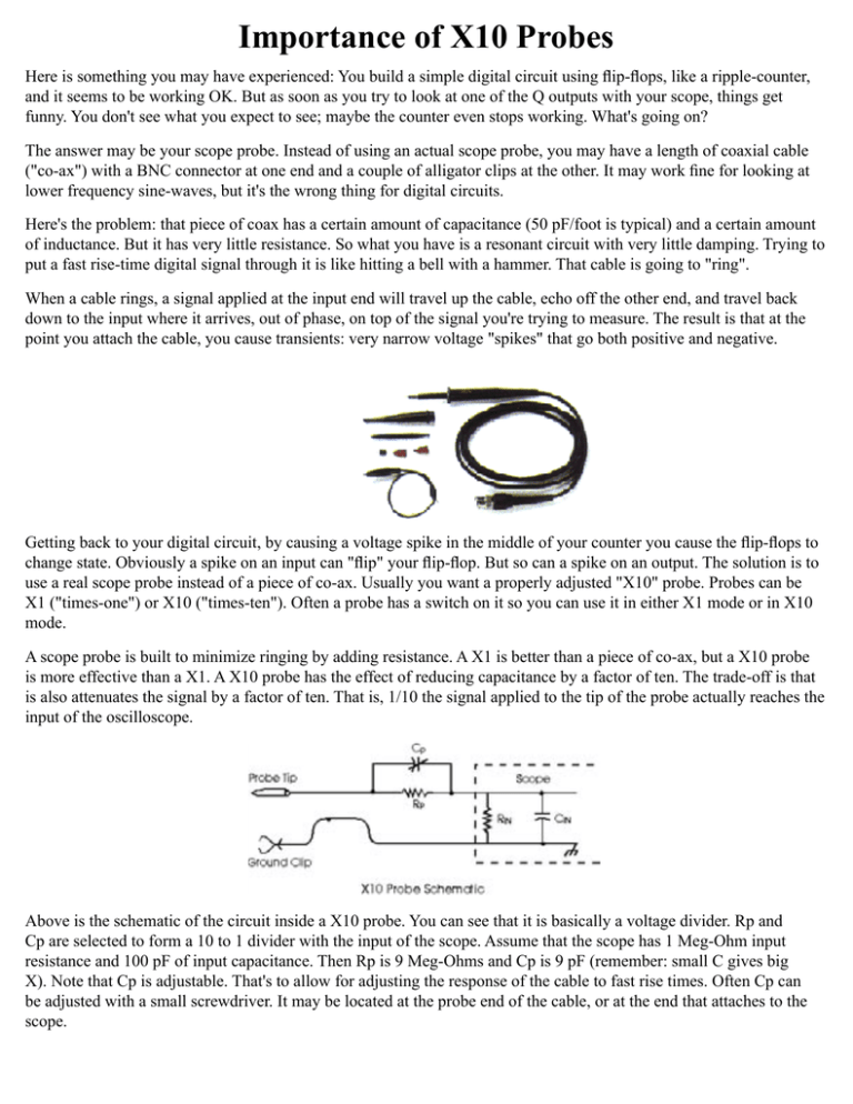
Importance of X10 Probes Here is something you may have experienced: You build a simple digital circuit using flip-flops, like a ripple-counter, and it seems to be working OK. But as soon as you try to look at one of the Q outputs with your scope, things get funny. You don't see what you expect to see; maybe the counter even stops working. What's going on? The answer may be your scope probe. Instead of using an actual scope probe, you may have a length of coaxial cable ("co-ax") with a BNC connector at one end and a couple of alligator clips at the other. It may work fine for looking at lower frequency sine-waves, but it's the wrong thing for digital circuits. Here's the problem: that piece of coax has a certain amount of capacitance (50 pF/foot is typical) and a certain amount of inductance. But it has very little resistance. So what you have is a resonant circuit with very little damping. Trying to put a fast rise-time digital signal through it is like hitting a bell with a hammer. That cable is going to "ring". When a cable rings, a signal applied at the input end will travel up the cable, echo off the other end, and travel back down to the input where it arrives, out of phase, on top of the signal you're trying to measure. The result is that at the point you attach the cable, you cause transients: very narrow voltage "spikes" that go both positive and negative. Getting back to your digital circuit, by causing a voltage spike in the middle of your counter you cause the flip-flops to change state. Obviously a spike on an input can "flip" your flip-flop. But so can a spike on an output. The solution is to use a real scope probe instead of a piece of co-ax. Usually you want a properly adjusted "X10" probe. Probes can be X1 ("times-one") or X10 ("times-ten"). Often a probe has a switch on it so you can use it in either X1 mode or in X10 mode. A scope probe is built to minimize ringing by adding resistance. A X1 is better than a piece of co-ax, but a X10 probe is more effective than a X1. A X10 probe has the effect of reducing capacitance by a factor of ten. The trade-off is that is also attenuates the signal by a factor of ten. That is, 1/10 the signal applied to the tip of the probe actually reaches the input of the oscilloscope. Above is the schematic of the circuit inside a X10 probe. You can see that it is basically a voltage divider. Rp and Cp are selected to form a 10 to 1 divider with the input of the scope. Assume that the scope has 1 Meg-Ohm input resistance and 100 pF of input capacitance. Then Rp is 9 Meg-Ohms and Cp is 9 pF (remember: small C gives big X). Note that Cp is adjustable. That's to allow for adjusting the response of the cable to fast rise times. Often Cp can be adjusted with a small screwdriver. It may be located at the probe end of the cable, or at the end that attaches to the scope. Most scopes have a "calibrator output" somewhere on the front panel. It supplies a square-wave to look at with your probe. Adjust Cp until the rising edge of the square-wave looks like Figure 2 below. Now you should be able to look at signals in your digital circuits without flipping your flops. Also, if you are using a frequency counter to measure the frequency of a digital signal, then ringing in the coax will give you a false reading. Again, the solution is a X10 probe. And that's today's technical tip.


