single phase to single phase step-down cycloconverter for
advertisement
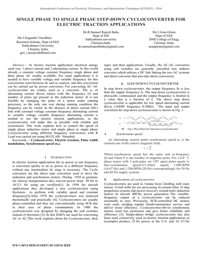
International Conference on Electrical, Electronics, and Optimization Techniques (ICEEOT) - 2016 SINGLE PHASE TO SINGLE PHASE STEP-DOWN CYCLOCONVERTER FOR ELECTRIC TRACTION APPLICATIONS Ms.J.Suganthi Vinodhini Research Scholar, Dept of EEE Sathyabama University Chennai, India giri_vino@rediffmail.com Dr.R.Samuel Rajesh Babu Dept of EIE Sathyabama university Chennai,India dr.samuelrajeshbabu@gmail.com Abstract— In electric traction application electrical energy used was: 1.direct current and 2.alternating current. In this world already a constant voltage constant frequency single phase and three phase AC readily available. For some applications it is needed to have variable voltage and variable frequency for this conversions need between dc and ac sources, and this conversion can be carried out by power converters. For converting AC–AC cycloconverter are widely used as a converter. The ns of alternating current drives relates with the frequency (f) and number of poles (p) present in the induction motor .It is not feasible by changing the poles of a motor under running processes, so the only one way during running condition the frequency can be varied. In the absence of direct current (DC) link with constant voltage constant frequency alternating current to variable voltage variable frequency alternating current is needed to run the electric traction applications, so the cycloconverter will make this as possible with reliable and economical. This work explains how to control the speed of single phase induction motor and single phase to single phase Cycloconverter using different frequency conversions with R Load was carried out using MATLAB / Simulink. Keywords— Cycloconverter, Electric traction, Pulse width modulation, Synchronous speed (ns). I. INTRODUCTION In electric traction applications the ac power at one frequency is converted openly to an ac power at a different frequency without any intermediate dc stage is necessary .The Cyclo converters are the direct type converters used to drive the induction and synchronous motors. During 1930 in germany for railway transportation they convert power from 50 Hz to 16-2/3 Hz using arc rectifiers[1] .In 1950 for aircraft applications they developed a new cycloconverter using thyristors to perform with variable speed and constant frequency[2].After 1970 the cycloconverters was analyzed theoretically and practically [4]. Cycloconverters are usually phase-controlled and they are conventionally using SCR due to their ease of phase commutation. In 1980 the cycloconverter was designed by changing the soft switches instead of thyristors [3]. In this IGBTs are used for converting AC to AC.This work explains about the Cycloconverter, their 978-1-4673-9939-5/16/$31.00 ©2016 IEEE Mr.J.Aran Glenn Dept of EEE DMI College of Engg Chennai, India aranglenn@gmail.com types and their applications. Usually, the AC-AC converters using soft switches are generally classified into indirect converter which utilizes a DC link linking the two AC systems and direct converter that provides direct conversion. II. STEP DOWN CYCLOCONVERTER In step down cycloconverter, the output frequency fo is less than the supply frequency fs. The step down cycloconverter is physically commutated and the output frequency is limited to a value that is a fraction of fi. The above step down cycloconverter is applicable for low speed alternating current drives (16MW frequency 0-20Hz). The input and output waveform for step down cycloconverter is shown in Fig .1. III. A. Fig.1.Waveform for step-down cycloconverter Synchronous speed An alternating current motor synchronous speed ns, is the rotation rate of the stator's magnetic field, Where synchronous speed has the same unit as frequency (f) and where P is the number of magnetic poles. For a 6-P 3phase motor with 3 pole-pairs set 120° apart, poles equals 6, thus synchronous speed=f/3 which equals 1,000 RPM (16.67 Hz) and 1,200 RPM (20 Hz) correspondingly for 50 Hz and 60 Hz supply systems. B. Applications of cycloconverter Cycloconverters are used in 1)mine hoist 2)rolling mill main motors 3) ball mills for ore processing 4) cement kilns 5) ship propulsion systems slip power recovery wound-rotor induction motors 6) aircraft 400 Hz power generation. The variablefrequency output of a cycloconverter can be reduced essentially to zero. Previously, SCR-controlled DC motors were used, needing regular brush/commutator service and deliver lesser efficiency. Cycloconverter-driven synchronous motors need less protection and give better reliability and efficiency [5]. Single-phase bridge cycloconverter has also been used extensively used in electric traction applications to (example) produce 25 Hz power in the U.S. and 16 2/3 Hz power in Europe[6]&[7]. while phase-controlled converters including cycloconverter are progressively being replaced by faster PWM self-controlled converters based on IGBT, GTO, MESFET and other switching devices. III. SIMULATION RESULTS A. Simulation results for Total Harmonic Distortion using FFT analysis The Simulink model is shown in Fig.2&4. The objective of this work is to analyze the speed of induction motor for variable frequencies Fig. 3&5 shows the FFT analysis by the total harmonic distortion for 100-1000 cycles was analyzed. The input frequency waveform for 50HZ and for output frequency waveform of 25HZ and 17 HZ (step down) using MATLAB simulink is shown in Fig. 6, 7&8. Fig.7.Output Waveform of 25HZ using MATLAB simulink Fig.8.Output Waveform of 17HZ using MATLAB simulink The output of MATLAB/simulink shows input frequency is 3 times the output frequency of the 1-phase Cycloconverter. The simulation starts with the 50 Hz input sine wave is generated. From the above discussion and from the waveform the input frequency is greater than the output frequency ant thereby this step-down cycloconverter can be utilize for traction applications under 25Hz frequency. Table 1. Frequency Vs Speed S.no 1 2 3 Fig.2.Simulink for Stepdown cycloconverter using IGBT Frequency(Hz) 17 25 50 Synchronous speed (rpm) 340 500 1000 Fig.3.FFT analysis Total harmonic distortion for step-down cycloconverter using IGBT Fig.4.Simulink for Stepdown cycloconverter using MOSFET Fig.9.Graph for Frequency Vs Speed Table.2. Comparison for soft switches in cycloconverter S.No SOFT SWITCHES THD(%) 1. 2. Fig.5.FFT analysis Total harmonic distortion for step-down cycloconverter using MOSFET. B. Simulation results for input and output wavefroms for stepdown cycloconverter using IGBT Figures and Tables Fig.6.Input waveform for 50HZ using MATLAB simulink IV. IGBT 0.45 MOSFET 0.47 CONCLUSION In this work, the model of Cycloconverter operation using MATLAB/Simulink software has been carried out. Simulation result is feasible to realize the designed cycloconverter in various basic AC –AC converter as a step-down frequency changer. In this work the total harmonic distortion is reduced as 0.02% by changing the softswitches in cycloconverter design. . References [I] H. Rissik, Mercury-Arc Current Converters. London, England: Sir Isaac Pitman and Sons, 1935. [2] K. M. Chirgwin, and L. J. Stratton, "Variable-speed constant-frequency generator system for air crail," AIEE Trans. Appl. Ind., vol. 78, pt. 11, pp. 304-310, Nov. 1959. [3] B. R. Pelly, Thyristor Phase-Controlled Converters and Cycloconverters, Wiley, New York, 1971 [4] J. Brenneisen "A new concept drive system for a diesel electric locomotive with asynchronous traction motor", IEEE Trans. Ind. Appl., vol. IA-9, no. 4, pp.482 -491 1973 [5] C. Lander, Power Electronics, Second Edition, McGraw Hill, England, 1987 [6] B. Ozpineci, B.K. Bose, “A Soft-Switched Performance Enhanced High Frequency Non Resonant Link Phase-Controlled Converter for AC Motor Drive”, Conference Proceedings of IEEE-IECON, Aachen/Germany, 1998, vol. 2, pp 733-73 [7] Paul C. Krause, Oleg Wasynczuk, and Scott D. Sudhoff, “Analysis of Electric Machinery and Drive Systems”, 2nd ed., ISBN: 978-0-47114326-0, Wiley-IEEE Press, 2002.
