Attenuation and Phase Shift
advertisement
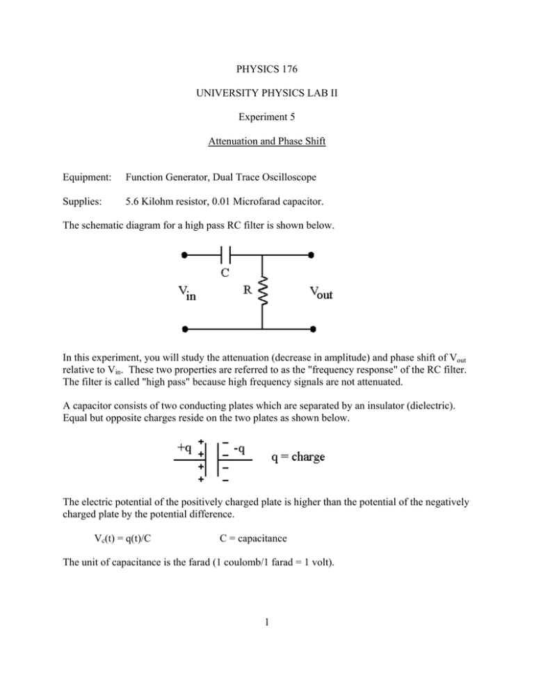
PHYSICS 176 UNIVERSITY PHYSICS LAB II Experiment 5 Attenuation and Phase Shift Equipment: Function Generator, Dual Trace Oscilloscope Supplies: 5.6 Kilohm resistor, 0.01 Microfarad capacitor. The schematic diagram for a high pass RC filter is shown below. In this experiment, you will study the attenuation (decrease in amplitude) and phase shift of Vout relative to Vin. These two properties are referred to as the "frequency response" of the RC filter. The filter is called "high pass" because high frequency signals are not attenuated. A capacitor consists of two conducting plates which are separated by an insulator (dielectric). Equal but opposite charges reside on the two plates as shown below. The electric potential of the positively charged plate is higher than the potential of the negatively charged plate by the potential difference. Vc(t) = q(t)/C C = capacitance The unit of capacitance is the farad (1 coulomb/1 farad = 1 volt). 1 Consider the circuit below which shows the instantaneous charge q(t) and current i(t). Since the capacitor represents an open circuit, the current i(t) is the rate at which the capacitor is charging. i(t) = dq/dt (1) The output voltage is the iR potential drop across the resistor. Vout = i(t)R (2) The charge on the capacitor q(t) and current i(t) are out of phase. As the charge builds up on the capacitor the current in the circuit drops. For example, if the current is i(t) = Ipsinωt, where ω = 2πf (f = frequency) (3) then the charge is q(t) = -(Ip/ω) cosωt = (Ip/ω) sin(ωt - π/2) (4) Thus the charge lags behind the current by π/2 radians (90E). The input and output voltages are Vin = -(Ip/Cω)cosωt + IpR sinωt = Ip [Rsinωt –(1/Cω)cosωt] Vout = IpR sinωt (5) The input voltage can be expressed compactly as Vin = IpZ sin(ωt - θ) (6) where Z is called the impedance of the series RC circuit and θ is the phase angle (in radians) by which Vin lags behind Vout. 2 The impedance of the series RC circuit is Z = R 2 + (1 / Cϖ ) 2 (7) and the phase angle is given by tan θ = 1/(RCω) (8) The impedance Z is the A.C. analog of resistance. Procedure - Experiment 5 1. Measure R with the digital ohmmeter and record. 2.. Begin lab by practicing scrambling and un-scrambling the function generator and oscilloscope. By the end of today's lab it is imperative for you to be comfortable with both these instruments. 3. Using the scope set the function generator to produce a 10 V(pp) sine wave. This signal will be used for the input in today's experiment. Do not change the amplitude of this signal during the experiment. 4. Set up the high pass RC filter. Use the function generator to apply a 10 V(pp) sine wave signal to the input. Use the dual trace oscilloscope to look at both Vin and Vout. Be sure that the two oscilloscope probes have their grounds connected to the function generator ground. 5. For several frequencies between 20 Hz and 20 kHz (the audio frequency range) measure the peak-to-peak amplitude of Vout. Check often to see that Vin remains at 10 V(pp) and that VOLTS/DIV dials are in their calibrated positions. From your measurements determine the ratio Vout Vout ( pp) = Vin Vin ( pp) and compute this ratio by using the formula Vout RCϖ = Vin [( RCϖ ) 2 + 1]1 / 2 (9) 3 6. For each listed frequency between 20 Hz and 20 kHz, measure the phase shift angle θ. The diagram below shows Vin lagging behind Vout. The phase shift angle in radians is θ = (∆ T/T) x 2π. 7. Compute the phase shift angle for each frequency. 4 Data Sheet - Experiment 5 Name R = ______________kΩ Section # _____________________ Frequency ω = 2πf (rad/sec) Vout (Volts) Measured Vout /Vin T (div) Phase shift θ (rad) θ = ( ∆T/T)×2π Calculated Vout /Vin (use eq. 9) 20 Hz 50 Hz 100 Hz 200 Hz 500 Hz 1 kHz 2 kHz 5 kHz 10 kHz 20 kHz Frequency ∆T (div) 20 Hz 50 Hz 100 Hz 200 Hz 500 Hz 1 kHz 2 kHz 5 kHz 10 kHz 20 kHz 5 Phase shift θ (rad) computed from tan θ = 1/(RCω) When you finish today's experiment, spend some time practicing with the oscilloscope. Explain why is acceptable to measure ∆T and T in units of "divisions" instead of "seconds." 6
