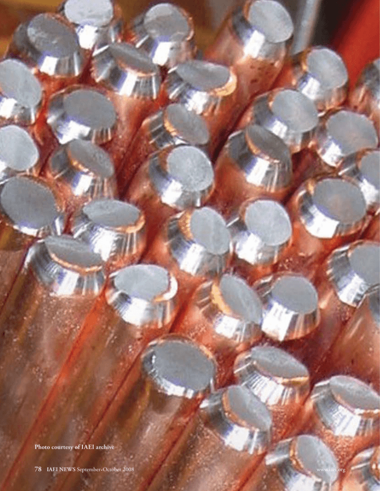
Photo courtesy of IAEI archive
advertisement

experimental evaluation of the corrosion performance Photo courtesy of IAEI archive 78 IAEI NEWS September.October 2008 www.iaei.org experimental evaluation of the corrosion performance Experimental Evaluation of the Corrosion Performance of Copper-Bonded and Galvanized Grounding Electrodes by F. D’Alessandro (B.App.Sc., B.Ed. PhD, SMIEEE) and B. Baumgartner Abstract A lightning discharges captured by lightning protection systems and for the effective operation of surge protection devices. Modern electronic equipment relies on an effective grounding system to provide a signal reference for low voltage digital signals. Utilities rely on effective grounding to prevent the flashover of insulators on transmission lines and to protect expensive equipment used on distribution systems. The performance of the grounding system is dependent upon the effective operation of its components— conductors, connectors and electrodes. Failure of any one of these components renders the entire system ineffective and increases the risk of injury or death to people and costly damage to equipment. Since the majority of a grounding system is concealed in the harsh underground environment, inspection of the components is virtually impossible. Therefore, the initial selection of Introduction The most important functions of a grounding system components is extremely important with regard to the are to protect people and equipment. It achieves this long-term effectiveness of the grounding system. The by minimizing the potential difference between non- components should possess excellent electrical conduccurrent-carrying conductive objects and the earth, ef- tivity and mechanical robustness, be able to withstand fectively reducing the risk of electrical shock. The repeated fault and surge currents, and be resistant to grounding system is also essential for the safe and ef- corrosion. Ideally, the grounding system components fective dissipation of the large transient currents due to should have a service life equal to that of the facility. variety of different electrodes is used for providing effective and safe electrical grounding. The ability of these electrodes to resist corrosion determines their useful service life. Copper-bonded steel and galvanized steel electrodes have been used for decades yet there is still much debate regarding the relative corrosion performance of each type of coating for applications in varying soil types and conditions. This article presents the experimental method and results from a series of laboratory corrosion tests that were carried out under controlled conditions on a range of electrode samples with both coating types in order to simulate their corrosion in soil according to an international standard. The results demonstrate there are distinct differences in performance between the two coating types. www.iaei.org September.October 2008 IAEI NEWS 79 experimental evaluation of the corrosion performance Vertically driven, coated, steel ground rods constitute the most common form of electrode utilized in a grounding system. Since ground rods are exposed to much more harsh conditions than any aboveground conductors or those utilized inside a structure, the ability of these electrodes to resist corrosion in a wide variety of soil types ultimately determines their useful service life. Hence, the corrosion performance of the electrode, which, for the purpose of the comparisons and discussion in this paper, will be defined as the mean time to failure of the electrode due to corrosion, is a very important consideration. Corrosion itself is a complicated phenomenon that has been the subject of decades of study and prevention. Unfortunately, this knowledge and expertise has not necessarily permeated electrical fora. Hence, there is often a lack of understanding with regard to differences between copper-bonded and galvanized carbon-steel ground rods. The answer primarily lies in the ability of the two coating materials, namely copper and zinc, to resist all forms of corrosion, namely, galvanic, electrolytic, and chemical. Bearing these factors in mind, the aim of the present paper is to evaluate and compare the corrosion performance of copper-bonded and galvanized steel ground rods. As part of this study, we carried out an extensive literature search. Surprisingly, there is very little published information on this topic, particularly from the viewpoint of a comparative experiment. Many studies have focussed on galvanized conductors, presumably because of their widespread use in the construction industry. For example, an Australian study successfully evaluated the corrosion rates of buried galvanized wires in a variety of different soil types (Jeffrey1). In another study, corrosion rates of galvanized screw anchors in 2 soil were measured over a 7-year period (Rabeler ). The study showed that more than half the zinc coating could disappear in 4 years. In another 7-year study based on a variety of different soils in Sweden, the authors found that the 165 µm zinc coating on some of the carbon steel samples corroded at a rate of 22 µm/yr, i.e., would com3 pletely corrode in 7–8 years (Camitz & Vinka ). In the next section of the paper, we describe the experimental procedure used to carry out a comparative evaluation of the corrosion performance of copperbonded and galvanized steel ground rods. Obviously, when a grounding system is designed, installed and commissioned, none of the persons involved need the additional burden of having to evaluate or certify the longevity of the system. Therefore, in the experiments described in our paper, all testing was carried out using a “worst-case” approach. Then, in the remainder of the paper, we present the results, a summary of the findings and our conclusions. Experimental procedure The experimental procedure followed four main steps: (i) Evaluation of the damage that occurs to the ground rod coating as it is driven into the soil; (ii) Preparation of a variety of ground rod samples for testing, including simulation of the installation damage determined from (i); (iii) Accelerated corrosion testing for a period of 28 days according to a European standard; (iv) Removal and evaluation of the samples following the 28-day test period. Evaluation of installation damage In order to simulate realistic but relatively harsh installation conditions, copper-bonded ground rods were driven a distance of approximately 1 m into rocky terrain. The samples were then carefully excavated and observed for damage. Photo 1 illustrates the installation and typical damage resulting from driving a ground rod into rocky terrain. Note that the installation damage did not penetrate the protective layer of copper to expose the carbon steel core. Two different types of installation damage were observed from these trials. One was long and sharp scratching damage, produced from forcefully sliding past a sharp stationary object. The scratches ranged from 2 to 8 inches in length. The second type of damage observed was short, from 0.04 to 2 inches in length, and blunt. Like the scratching damage, this denting effect did not appear to remove any material, although the depth was not uniform. Preparation of ground rod samples A batch of 27 unique ground rod sample types was prepared, with two samples for each type, i.e., a total of 54 sample rods. Each ground rod sample was cut with a band saw to a length of 20 inches, exposing bare steel on each end. The cut surface and edges were polished with a belt sander. About half of the rod samples were prepared specially to mimic the two types of damage observed from the installation trials. The special preparation procedure was as follows: (i) Worst-case scratching damage was simulated by creating an 8-inch scrape along the rod. A template 80 IAEI NEWS September.October 2008 www.iaei.org experimental evaluation of the corrosion performance Photo 1(b). Typical “installation damage” to the ground rod coating Photo 1(a). Example of driven ground rod was taped to each sample before creating the scratch to ensure precision. The ground rods were held in place with a v-block and a kick press was used to produce the desired damage. No material was removed from the ground rods during this process. The impact produced an indentation similar to what was observed from the installation trials. (ii) Duplicating the denting damage was very difficult because of the variability observed in the field trials. However, it was possible to create a consistent cavity using a hydraulic press that provided some degree of similarity to the observed denting damage. Six indentations, 0.8 inches apart, were created on each sample. The typical diameter of the indentations was about 0.25 inches and the depth ranged from 0.04 to 0.08 inches. The process is illustrated in photo 2. Prior to commencing the accelerated corrosion tests, measurements of mass, diameter, length, and resistance for each sample were taken and recorded (and exactly the same measurements were taken and recorded upon completion of the tests). The mass of each rod was measured with a calibrated Toploader Balance GX-800, accurate to 0.001 grams, after being dried with a nonabrasive cloth. The diameter of each rod was measured at three points (near the ends and in the middle) uswww.iaei.org ing a calibrated Mitutoyo Absolute Digimatic Calipers with an accuracy of 0.4 mil. Lengths were measured with an accuracy of 0.02 inches. The resistance of each sample was measured with a digital ratiometric microohmmeter DRM-40 along three different 100 mm sections (near the ends and in a central position) with an accuracy of 0.01 μΩ. Corrosion test procedure The accelerated corrosion testing on the samples was carried out in strict accordance with an internationally accepted4 standard, namely the European Standard EN 50164-2 . Each specimen was inserted into its own clean PVC “test tube” created from a 20-inch length of pipe with an end cap. The diameter of the PVC tubes was 2 inches, so the volume of solution was greater than ten times the volume of the specimen. Each rod sample was inserted into the tube and then totally immersed in a non-stirred purified water solution containing calcium chloride (CaCl2) and sodium sulphate (Na2SO4). The characteristics of the aqueous solution were as follows: 1 litre of distilled H2O, 650 mg of CaCl2, 1500 mg of Na2SO4, liquid temperature 20°C and a pH in the range 5–9. The open end of each tube was loosely sealed with a piece of plastic wrapping and a rubber band in September.October 2008 IAEI NEWS 81 experimental evaluation of the corrosion performance Photo 2(a). Hydraulic press setup order to minimize evaporation of the corrosive solution. Once immersed, the samples were left in solution and the tubes hung in a climate-controlled room (set at 20°C) for a period of 28 days without disruption. Part of the final line-up of 54 tubes is shown in photo 3. Removal and measurement of the samples At the end of the 28-day test period, all of the samples were removed from solution, washed and dried. The washing and drying procedure was carried out in such a manner as to preserve the integrity of the results. The samples were washed under running tap water, rinsed with de-ionized water, partially dried with a soft cloth and completely dried with a heat gun. Each sample was Photo 2(b). Indentations were made using a template (Details: 6 indentations, 0.8” apart, 0.25” in diameter, 0.04” - 0.08” in depth). 82 IAEI NEWS September.October 2008 www.iaei.org experimental evaluation of the corrosion performance Photo 3. Line-up of ground rod samples in labelled PVC tubes then placed in a clean zip-lock plastic bag until final measurements could be taken. The final measurements were taken in the same way as the pre-test measurements, comprising the mass, diameter, length, and resistance of each ground rod sample after 28 days in the corrosive solution. Results Table 1 shows the results of the corrosion performance testing carried out on the 27 unique ground rod types (with two samples per type) according to the procedure described in Section 2, Experimental procedure. Photo 4 shows a typical copper-bonded and galvanized ground rod specimen after removal from the corrosive solution. www.iaei.org Discussion In order to comply with EN 50164-2, the results for a 4 ground rod need to satisfy the following criteria : Electrical resistance over a 100 mm length measured after the tests shall not exceed the resistance value measured before the tests by more than 50%. Base metal shall not exhibit any visual corrosive deterioration. Specimens shall be of a smooth profile with blended radii (no sharp corners). With regard to the change in electrical resistance, all of the ground rod samples were very similar in performance, undergoing a mean increase in resistance of about 5% after corroding in solution for 28 days. So, the first criterion was met by all rod types. With regard September.October 2008 IAEI NEWS 83 experimental evaluation of the corrosion performance Table 1: Results from comparative tests, according to EN 50164-2, of the corrosion performance of a variety of copper-bonded and galvanized ground rods. to the other two criteria, none of the corroded samples showed signs of the base metal (carbon steel) or any sharp features. So, all three criteria were met by all rod samples. On the other hand, the results reveal significant differences in the rate of corrosion (and, hence, useful lifetime) between copper-bonded and galvanized rods. The mean mass loss across all copper-bonded rod samples was 144 mg over the 28-day test period, whilst for galvanized rods it was 213 mg. The mean mass loss for raw steel rods was 224 mg, not significantly larger than the loss value of the galvanized rods. On face value, this result means that the zinc coating on galvanized rods corrodes at a rate which is almost 50% faster than a copper coating. In fact, the difference is larger than this because the mean coating thickness for the whole copper-bonded rod sample set (about 6.9 mil) was more than double that of the galvanized rods (typically only 3 mil because thicker zinc coatings tend to crack if the rod is bent). Hence, if the percentage difference in mass loss over 28 days is referenced back to the amount of original metal coating, we find that the corrosion rate of galvanized rods is 3.38 times of the rate for copper-bonded rods. In other words, a grounding system based on galvanized rods typically has a lifetime of less than one third that of a system based on copper-bonded rods. Upon closer inspection of the individual results in table 1, it appears that the four copper-bonded rods with “copper-based exothermically-welded end-termi- 84 IAEI NEWS September.October 2008 www.iaei.org experimental evaluation of the corrosion performance Photo 4(a) Photo 4(b) Photo 4. Typical ground rod specimens after removal from solution at the completion of the 28-day accelerated corrosion test period. (a) Copper-bonded rod. (b) Galvanized rod. nations” (CBEWET), which prevent exposure of the bare steel ends to the corrosive solution, produced results that are somewhat different to the rest of the copper-bonded rod samples. For example, the mean mass loss for those four rods was 42 mg, about one third of the mean value for the whole copper-bonded rod data set. If these four rods are removed from the copper vs. galvanized analysis presented in the previous paragraph, the absolute mean mass loss for the copperbonded rods is 178 mg. The face-value comparison for galvanized rods is then a corrosion rate which is 20% faster. More importantly, if a relative comparison is carried out based on the original amount of rod coating, we find that the corrosion rate of galvanized rods is 2.73 times the rate for copper-bonded rods. In other words, a grounding system based on galvanized rods typically has a lifetime of just over one-third that of a system based on copper-bonded rods. It is also possible to analyse the mass loss data in table 1 further by making comparisons across common groupings of coating thickness, rod diameter and electrode damage (hammered and scratched). Table 2 shows the differences in the results. Once again, although the results were extraordinarily good for rod samples with copper-based exothermically-welded end-terminations, they were removed from the analysis in order to obtain the most conservative and objective comparisons. www.iaei.org The first two rows show the results discussed in the preceding paragraphs. The remaining results are also interesting. First, this experiment has clearly established that the damage-simulated samples exhibit no difference in corrosion performance to rods without damage. Second, the mean mass loss values are very consistent for all types of copper-bonded rods with regard to coating thickness and rod diameter. The same can only be said for galvanized rods with regard to coating thickness. The galvanized rod results related to diameter show a significantly larger mass loss for the rods of diameter 5/8 inch. Presumably, this is due to the larger surface area of contact with the corrosive solution. With regard to the results for the change in diameter of the rod samples, logically, one would expect these data to be correlated with the mass loss results. Despite the fact that the percentage uncertainty in individual diameter data is quite large, the overall mean values were well-correlated with the mean mass loss values. The mean decrease in diameter for copper-bonded and galvanized rods, with an uncertainty in each value of about ± 0.1 mil, was 0.43 and 0.67 mil respectively. In other words, the mean mass loss is about 50% more for galvanized rods. Finally, it is worth comparing the results of the present quantitative study, which was carried out under an accelerated test procedure in a laboratory, with historiSeptember.October 2008 IAEI NEWS 85 experimental evaluation of the corrosion performance Table 2: Comparison of mass loss results from table 1 across common groupings of coating thickness, rod diameter and installation damage simulated by hammering and scratching. cal field data. From 1910 to 1955, the US National Bureau of Standards (NBS) conducted an extensive underground corrosion study5 in which 36,500 specimens, representing 333 varieties of ferrous, non-ferrous and protective coating materials were exposed in 128 test locations throughout the USA. Table 48 of this report presents data for copper pipe specimens buried in 43 different soils for a period of 8–13 years. Using the data from this study, it is readily seen that that 10 mil of copper, the typical copper-bonded rod coating thickness, will provide a service life in most soils of at least 30–40 years. This is a conservative estimate as it assumes a constant rate of corrosion, whereas corrosion theory and also the US NBS study5 showed that the corrosion rate decreased with time. On the other hand, as part of the same long-term study, in 1924 an underground exposure test was initiated on a series of 5 different base metals to which a series of zinc coatings were applied by the hot-dip process. This test was carried out for 10 years, involving hundreds of galvanized pipe specimens with a zinc coating thickness in the range 3–9 mil. The results showed that, for most of the soils, zinc coatings of 3.5 mil or less were destroyed during the 10-year exposure period and pitting of the underlying steel occurred. A typical galvanized ground rod has a coating thickness of 3–4 mil, so it can be concluded that the service life of a galvanized rod is 10–15 years. In another past study, the Naval Civil Engineering Laboratory (NCEL) conducted a 7–year program of testing metal rods for electrical grounding 6. Copper- bonded, stainless clad, and galvanized steel rods were included, among other materials. Although this study was not nearly as rigorous or quantitative as the one undertaken by the NBS, the report concluded “magnesium, aluminum, zinc, mild steel and galvanized steel rods did not have the desired corrosion resistance”. In summary, the NBS study, supported by the NCEL study, showed that a typical galvanized ground rod has a service life of 10–15 years whilst a typical copper-bonded ground rod has a service life of 30–40 years. In our accelerated corrosion study presented in this paper, we found that galvanized rods will corrode at about 3 times the rate of copper-bonded rods. Hence, this result is in excellent agreement with the historical field data. Conclusions This article has presented the experimental method and results from a comparative evaluation of the corrosion performance of copper-bonded and galvanized steel ground rods. The whole procedure revolved around the realistic simulation of the corrosion of a range of rod samples in soil using a controlled, laboratory-based accelerated corrosion test according to the standard EN 50164-2. The main conclusions that can be drawn from our study are as follows: 1. Galvanized ground rods will corrode at a significantly faster rate than their copper-bonded counterparts. 2. The zinc coating on galvanized rods corrodes at 86 IAEI NEWS September.October 2008 www.iaei.org experimental evaluation of the corrosion performance 4 CENELEC, “EN 50164-2 Lightning protection components (LPC) about 3 times the rate of the copper coating on copperPart 2: Requirements for conductors and earth electrodes” (2002): Annex B. bonded rods. 5 Romanoff, M., “Underground Corrosion”, US Dept. of Commerce, 3. A grounding system based on typical galvanized National Bureau of Standards, Circular 579 US Govt. Print. Off (April 227 pages, ASIN: 0007DQG9Y. rods will have a lifetime of about one third that of a 1957). 6 Drisko, R.W., “Field Testing of Electrical Grounding Rods”, Naval Civil Engineering Laboratory, Port Hueneme, California, US Dept. of system based on typical copper-bonded rods. 4. Our results are in excellent agreement with a 50- Commerce, National Technical Information Service, February 1970. year old National Bureau of Standards field study, which Franco D’Alessandro has more than a decade in of experience the field of lightning protection and groundshowed that galvanized and copper-bonded rods have a ing, where he worked as a senior research scientist and service life of 10–15 and 30–40 years respectively. R&D product engineer, both in Australia and the 5. Within the uncertainties and statistical variation United States. He recently became the Managing Director & of the experiment, the results showed that typical instalPrincipal Consultant for PhysElec Solutions Pty Ltd, lation damage such as scratches and dents on the coatan Australian consultancy services company that delivers global soluing of ground rods does not affect the corrosion perfor- tions in electrical engineering and applied physics, with specialisation mance of the rods. in lightning, surge & transient protection, earthing & grounding, high voltage engineering and power electronics. References Jeffrey, R., “Corrosion rates of buried galvanised wires”, Corrosion & Prevention 98 Proceedings (1998): 316­–320. 2 Rabeler, R.C., “Soil Corrosion Evaluation of Screw Anchors”, Effects of Soil Characteristics on Corrosion (1989): 54–80. 3 Camitz, G., Vinka, T.G., “Corrosion of Steel and Metal-Coated Steel in Swedish Soils – Results of Field Exposures”, Proceedings of 10th Scandinavian Corrosion Congress NKM10 (1986): 305–312. 1 Brian Baumgartner is studying Electrical Engineering at Purdue University, USA. He has had work experience with ERICO Inc. and Whirlpool Inc. where his role was as an Applications Engineer Dishwasher User Interface and Controls Engineer respectively. His special interest is in electronic control systems and electronic motion devices. Secure Your Grounding Project More Effectively Why get your information piecemeal, when you can see design, engineering, installation and enforcement perspectives dovetail together in this one book? Soares Book on Grounding and Bonding is the only book on the market that helps you see all the perspectives before you do the job. Meticulously updated to NEC-2008, this 10th edition authoritatively reviews each topic from the perspectives of the enforcers. Get your copy today! Product No. 357009 $50.00 (Member: $45.00) 1-800-786-4234 www.iaei.org September.October 2008 IAEI NEWS 87


