variable resistor - Moranbah Weather
advertisement

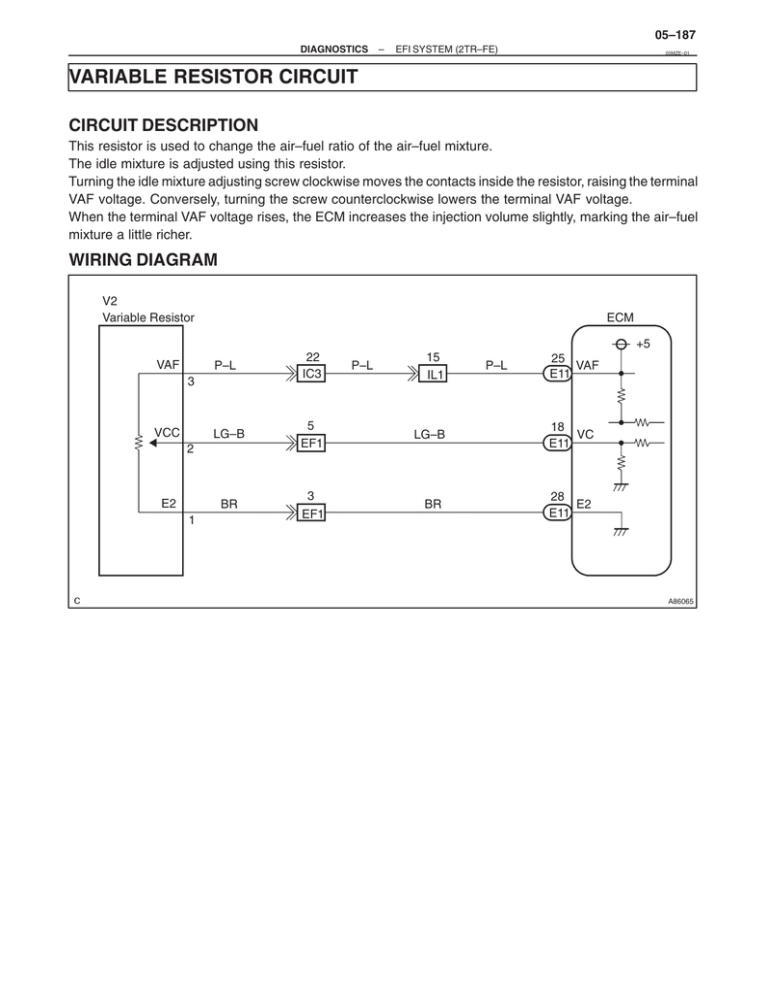
05–187 DIAGNOSTICS – EFI SYSTEM (2TR–FE) 05MZE–01 VARIABLE RESISTOR CIRCUIT CIRCUIT DESCRIPTION This resistor is used to change the air–fuel ratio of the air–fuel mixture. The idle mixture is adjusted using this resistor. Turning the idle mixture adjusting screw clockwise moves the contacts inside the resistor, raising the terminal VAF voltage. Conversely, turning the screw counterclockwise lowers the terminal VAF voltage. When the terminal VAF voltage rises, the ECM increases the injection volume slightly, marking the air–fuel mixture a little richer. WIRING DIAGRAM V2 Variable Resistor ECM +5 VAF P–L 22 IC3 LG–B 5 EF1 LG–B 18 VC E11 BR 3 EF1 BR 28 E2 E11 3 VCC 2 E2 1 P–L 15 IL1 P–L 25 VAF E11 A86065 05–188 DIAGNOSTICS – EFI SYSTEM (2TR–FE) INSPECTION PROCEDURE NOTICE: Always use a CO meter when adjusting the idle mixture. If a CO meter is not available, DO NOT ATTEMPT TO ADJUST IDLE MIXTURE. 1 CHECK CO/HC CO Meter A70831 (a) (b) (c) (d) (e) (f) (g) (h) (i) (j) Warm up the engine to normal operating temperature. Switch all accessories OFF. Connect all vacuum lines properly. Connect the tachometer. Check ignition timing correctly. Check idle speed correctly. Check that the CO meter is properly calibrated. Race the engine at 2,500 rpm about 2 minutes. Insert a tester probe at least 40 cm (1.3 ft) into the tailpipe. Measure the concentration with 1 – 3 minutes after racing the engine to allow the concentration to stabilize. Idle CO concentration: 1.5 " 0.5% OK CHECK FOR PROBLEM SYMPTOMS TABLE (See page 05–8) NG 2 ADJUST CO CONCENTRATION SST 09243–00020 (a) (b) Put the vehicle in the same condition as step 1 this chart. Using SST, adjust the idle mixture by turning the idle mixture adjusting screw in the variable resistor. Result: SST Result Idle Mixture Adjusting Screw Connection: 1.5 " 0.5% B Change in CO connection C No change in CO connection A HINT: S Always check idle speed after turning the idle mixture adjusting screw. If it is incorrect, readjust idle speed. The idle mixture adjusting screw can be turned within 180 degrees. Do not turn this screw more than the specified. S 180_ B ADJUSTMENT COMPLETE C CHECK CO/HC (See page 14–1) A73579 A Proceed 05–189 DIAGNOSTICS 3 – EFI SYSTEM (2TR–FE) INSPECT VARIABLE RESISTOR SST 09243–00020 (a) 2 1 3 (b) SST Measure the resistance according to the value(s) in the table below. Resistance: Tester Connection Specified condition 1–2 3.5 to 6.5 Ω Measure the resistance according to the value(s) in the table below, when turning the idle mixture adjusting screw fully clockwise and counterclockwise using SST. Resistance: NG Tester Connection Specified condition 2–3 Change from about 5 kΩ to 0 kΩ accordingly REPLACE VARIABLE RESISTOR A74545 OK 4 CHECK ECM(VAF VOLTAGE) SST 09243–00020 (a) (b) Turn the ignition switch ON. Measure the voltage according to the value(s) in the table below ECM connector while slowly turning the idle mixture adjusting screw first fully counterclockwise and then fully clockwise, using SST. Voltage: Tester Connection SST VAF (E11–25) – E2 (E11–28) Specified condition Voltage changes smoothly from 0 V to about 5 V, i.e. does not suddenly jump up to 5 V down to 0 V E11 VAF E2 G38493 NG OK REPLACE ECM (See page 10–12) 05–190 DIAGNOSTICS 5 – EFI SYSTEM (2TR–FE) CHECK HARNESS AND CONNECTOR(VARIABLE RESISTOR – ECM) (a) (b) (c) Wire Harness Side Variable Resistor Connector V2 E2 VAF Disconnect the V2 variable resistor connector. Disconnect the E11 ECM connector. Measure the resistance according to the value(s) in the table below. Standard(check for open): VC A73587 Tester connection Specified condition VC (V2–2) – VC (E11–18) Below 1 Ω VAF (V2–3) – VAF (E11–25) Below 1 Ω E2 (V2–1) – E2 (E11–28) Below 1 Ω Standard(check for short): Tester connection E11 VAF VC ECM Connector A65159 OK REPLACE ECM (See page 10–12) Specified condition VC (V2–2) or VC (E11–18) – Body ground 10 kΩ or higher VAF (V2–3) or VAF (E11–25) – Body ground 10 kΩ or higher NG REPAIR OR CONNECTOR REPLACE HARNESS OR


