Little Cooler - Finish Thompson, Inc.
advertisement
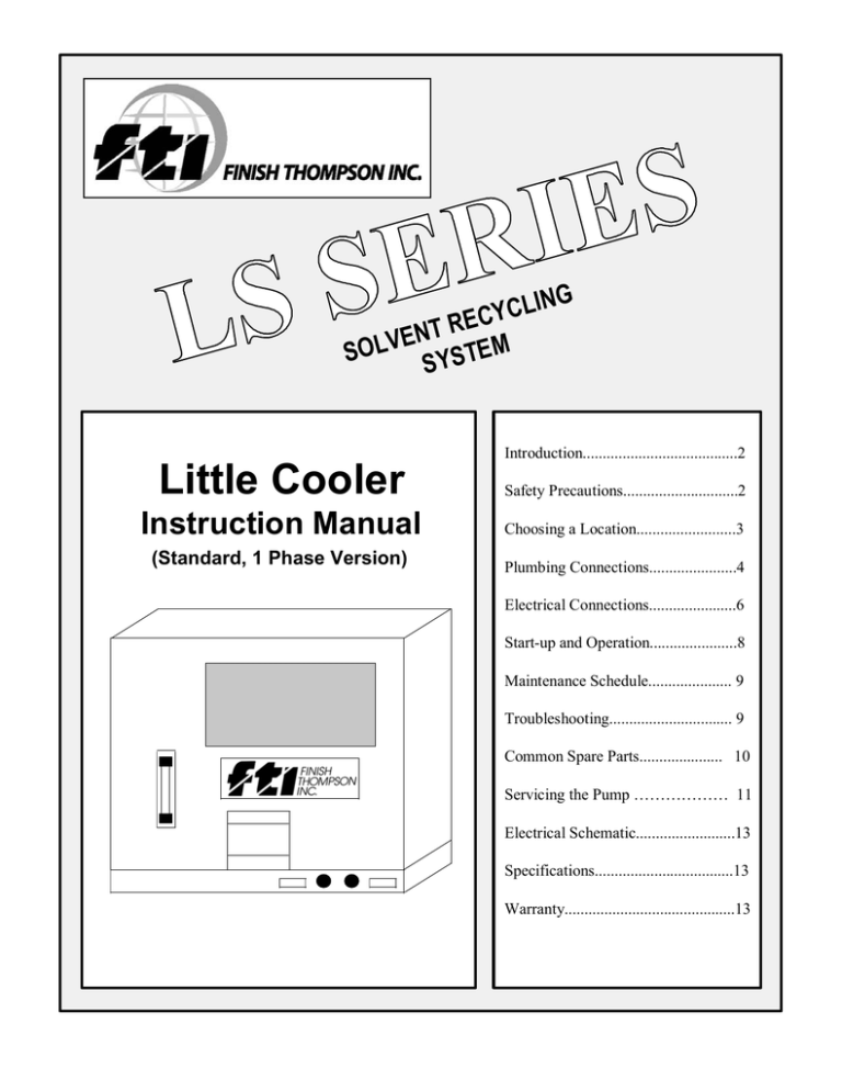
ING L C Y EC R T N E SOLV SYSTEM Introduction.......................................2 Little Cooler Safety Precautions.............................2 Instruction Manual Choosing a Location.........................3 (Standard, 1 Phase Version) Plumbing Connections......................4 Electrical Connections......................6 Start-up and Operation......................8 Maintenance Schedule..................... 9 Troubleshooting............................... 9 Common Spare Parts..................... 10 Servicing the Pump ……………… 11 Electrical Schematic.........................13 Specifications...................................13 Warranty...........................................13 Version 2.4 April 2003 INTRODUCTION The Little Cooler is a closed-loop cooling system designed to work with an FTI distillation system. Use of the Little Cooler can save money and conserve the environment by eliminating the continuous use of a clean water supply. Further, this air-cooled system uses no ozonedepleting gasses to perform its job. Quality engineered and manufactured, the Little Cooler requires minimal operator involvement and maintenance and can provide years of trouble-free service. The Little Cooler is compatible with all of FTI’s electrically heated LS-Series solvent distillation systems. SAFETY PRECAUTIONS WARNING: READ THIS MANUAL COMPLETELY BEFORE INSTALLING AND OPERATING THIS UNIT. FAILURE TO FOLLOW THESE PRECAUTIONS CAN RESULT IN SERIOUS INJURY OR DEATH. The Little Cooler is non-explosion proof and must be installed outside the hazardous area. Do not use the Little Cooler for processing solvents with boiling points below 150F. Ambient temperature of installation area must not exceed 100F. A qualified electrician should perform electrical wiring. Any electrical wiring or components connected to the Little Cooler that enter a hazardous area must conform to the explosion proof standards for that hazardous area. Store and keep all flammables and combustibles a safe distance from the unit. A minimum of 20 feet is required. Wear proper eye and skin protection when installing, operating, or maintaining this equipment. 2 CHOOSING A LOCATION Follow these requirements to determine a suitable installation location for the Little Cooler: Install outside of any hazardous areas. The horizontal distance (from the equipment being cooled) must be less than 50 feet. The vertical rise (to or from equipment being cooled) must be less than 12 feet. Ambient air temperature around the unit must not exceed 100F. Install the unit on a flat, level surface. It will be necessary to secure the base of the unit (using the mounting holes provided). The enclosure of the Little Cooler is weather resistant and is suitable for outdoor installation. Precautions must be taken to avoid direct sunlight and severe weather. LITTLE COOLER HAZARDOUS AREA 12 FT. MAX 50 FT. MAX DISTILLATION UNIT The front of the unit (where the electrical box and sight glass are located) must be in an open area and accessible at all times for performing routine maintenance. The top of unit and rear (where the radiator is located) must be in an open area to allow proper air circulation. A minimum of 12 inches of space is required on each side of the unit. 3 PLUMBING CONNECTIONS General plumbing instructions: Use a minimum of 5/8-inch (inside diameter) high temperature flexible hose or 1/2 inch piping to and from the Little Cooler for coolant circulation. Use sweep elbows or large radius bends to reduce frictional losses in the piping. Length of coolant lines must not exceed 50 feet. The WATER OUTLET of the Little Cooler plumbs to the condenser or WATER INLET of the distillation unit. The WATER OUTLET from the distillation unit’s condenser returns to the WATER INLET of the Little Cooler. If using a JetVac attachment with your solvent distillation system: 1) Install a tee into the coolant lines. Plumb the JetVac to the branch side of each tee (for both the water and the water out). 2) Install a ball valve on the water out side, after the tee to the JetVac unit (this is used to restrict the flow to the JetVac unit if the flow switch for the distillation unit is not being satisfied). Plumb a Y-strainer in line to the WATER INLET side of the distillation unit. This is to catch any foreign matter or debris that enters into the cooling system (Note: models LS-15IIE and LS-55IIE already have a Y-strainer factory-installed inside their cabinet). NOTE: When installing the Little Cooler to models LS-15IIE or LS-55IIE, the water solenoid valve inside the Still may need to be bypassed. The solenoid significantly reduces coolant flow capabilities, thereby hindering the performance of the Little Cooler. Whether or not this is required depends on the amount, type, and distance of plumbing between the Still and the Little Cooler. NOTE: Do not use the Little Cooler for the optional “Quick-cool” feature of an LS distillation system. Use tap water only for this feature. NOTE: If using the Little Cooler with an LS-15IIE or LS-55IIE refer to the “Special Plumbing Requirements...” section of this manual for additional instructions. 4 Special plumbing requirements for LS-15IIE/LS-55IIE models: NOTE: When installing the Little Cooler to models LS-15IIE or LS-55IIE, the water solenoid valve in the Still may need to be bypassed. This item significantly reduces the coolant flow capabilities, thereby hindering the performance of the Little Cooler. Never bypass the safety flow switch in your LS distillation unit. Procedure: 1) Simply cut the water solenoid valve from the water inlet hose and install a ½” H x ½” H hose-barb fitting in its place. 2) It is not necessary to disconnect the electrical connections to the solenoid or remove it from the unit. 3) Perform the plumbing to and from the Little Cooler according to the “General Plumbing Instructions” section of this manual. 5 ELECTRICAL CONNECTIONS General electrical instructions: The Little Cooler requires a switched 230-volt, 1 phase, 60 Hz, 20 amp electrical service with separate ground and circuit breaker. A qualified electrician should perform all electrical wiring. When installing outdoors, use only weather-tight electrical components. Run the electrical supply from your circuit breaker to your switch, then to the Little Cooler. Bring your 3-wire supply to the inside of the Little Cooler’s junction box. Connect your L1 supply to the two black wires, your L2 supply to the two red wires (use the wire nuts provided) and secure your ground to the junction box. Verify that L1 and L2 are secured and not shorting to ground. NOTE: If using the Little Cooler with models LS-15IIE or LS-55IIE, refer to the “Electrical Connections for Models LS-15IIE and LS-55IIE” section of this manual for additional instructions if automated start/stop operation is desired. ATTACH YOUR CONDUIT HERE JUNCTION BOX GROUND 6 Electrical Connections for Models LS-15IIE and LS-55IIE: The design of the LS-15IIE and LS-55IIE solvent distillation systems provides automatic termination of its cycle by time. Following the procedure below will allow a System II “E” to control the Little Cooler for automatic start/stop control. In addition, a timer in the LS unit will allow the Little Cooler to run for one hour after cycle termination to condense any vapors remaining in the LS unit’s boiling chamber. Materials required (customer provided): One 3/4 inch potted seal fitting (explosion proof) Potting material for above fitting Electrical conduit to reach from the LS unit to the Little Cooler 18/2 with ground (or larger) electrical wire of similar length One contactor: use a 2 pole, 20 amp, with 220 volt coil One electrical enclosure (water-tight) for the above contactor (to mount on Little Cooler) Instruction manual for the LS unit Procedure: 1. Disconnect main power supply to both the LS unit and the Little Cooler. 2. Run the electrical wire and conduit from the rear of the LS unit to the Little Cooler. 3. Install a potted seal fitting between the Still’s connection box and the conduit from the Little Cooler (make sure that the control wires to the Little Cooler run through this fitting). 4. Make the electrical connections (wires B and 1L2) and seal the potted fitting with approved potting material. The potted fitting is to prevent vapors from entering the conduit and leaving the hazardous area. 5. Mount the customer-supplied junction box and contactor to the Little Cooler near its main junction box. 6. Connect the two wires from the LS unit to the "coil" side of the contactor. Connect the 230volt incoming power (L1 and L2) to the "hot" side of the contactor, and the Little Cooler to the "cold" side of the contactor. Connect grounds as normal. CONTROL WIRES FROM STILL TO CONTACTOR’S COIL (WIRES B AND 1L2) JUNCTION BOX (CUSTOMER-SUPPLIED, MOUNTED TO THE LITTLE COOLER) MAIN POWER IN CONTACTOR (CUSTOMERSUPPLIED) POWER OUT TO LITTLE COOLER’S MAIN JUNCTION BOX GROUND 7 START-UP AND OPERATION Filling the system: NOTE: Use only distilled or treated water in the coolant mixture to prevent scale build-up in the cooling system and piping NOTE: Do not overfill or under fill the reservoir. Running the Little Cooler with improper coolant levels will damage the pumping system and void the warranty. 1. Remove the access panel on top of the Little Cooler. 2. Find and remove the plastic plug inserted into the reservoir cover to reveal the fill hole. 3. Fill the reservoir with a 50/50 mix of automotive (long-life, low silicate) antifreeze and distilled water. The system will hold 7 to 8 gallons (depending on your piping length). The reservoir is full when liquid is visible in the sight glass. 4. Start the system. After 5 minutes of operation, check the level of liquid in the sight glass. Top off the reservoir if the coolant level is low. 5. Reinstall the plug into the fill hole and replace the Little Cooler’s access panel. Operation: 1. Once installed, the little cooler requires minimal operator involvement. 2. Check the level of coolant in the sight glass. Top off if necessary. 3. Turn on the Little Cooler before starting the distillation system. 4. *Turn off the Little Cooler approximately 1 hour after shutting down the distillation system. This one-hour delay is necessary to condense solvent vapors remaining in the LS unit. * Not required if connected for automatic operation. 8 MAINTENANCE SCHEDULE CAUTION: ALWAYS WEAR EAR PROTECTION, SAFETY GOGGLES, PROTECTIVE CLOTHING, AND GLOVES WHEN WORKING ON OR WITH THIS UNIT. Each use: CHECK LIQUID LEVEL - Verify that the coolant in the reservoir tank is filled to the proper level. If low, top off with a 50/50 mix of automotive (long-life, low silicate) antifreeze and distilled water until liquid is visible in the sight glass. CHECK VENTILATION - Verify that no objects are placed against or around the unit that can restrict proper airflow through the Little Cooler. Monthly: HEAT EXCHANGE SYSTEM - Clean the finned-tube surfaces of the heat-exchanger by removing the front access cover and blowing compressed air through the fins from the inside to the outside. DEBRIS IN PLUMBING - Remove and clean the screen in the Y-strainer installed on the water inlet side of the distillation system. Annually: CHANGE THE COOLANT - Drain and flush (with water) the reservoir tank, piping, and heat exchanger and re-fill with a 50/50 mix of automotive (long-life, low silicate) antifreeze and distilled water. TROUBLESHOOTING The following are a few tips for diagnosing some problems you may experience during the use of your Little Cooler. If the following suggestions do not pinpoint the cause of your problem, contact FTI’s toll-free “Service Hotline”: 800-888-3743, 8 am to 5 pm EST, Mon. - Fri. CAUTION: ALWAYS WEAR EAR PROTECTION, SAFETY GOGGLES, PROTECTIVE CLOTHING, AND GLOVES WHEN WORKING ON OR WITH THIS UNIT. CAUTION: A QUALIFIED ELECTRICIAN SHOULD PERFORM ANY ELECTRICAL TESTS PERFORMED ON THIS UNIT. 9 PROBLEM: Unit will not turn on POSSIBLE CAUSES: Improper electrical hook-up. Verify proper installation of electrical supply. No power to the unit. Check main circuit breaker and/or electrical supply to the unit. PROBLEM: Fan runs, but not the pump. POSSIBLE CAUSES: NOTE: If the liquid temperature from the radiator exceeds 150F, a safety temperature switch will shut down the pump of the Little Cooler. The fan will continue to run to assist cooling the liquid. Once the liquid cools to below 100F, the pump will turn back on. Coolant level is low in the reservoir. Top off to proper level. Ambient air temperature too high. Verify proper ventilation of the unit. Heat exchange system dirty. Clean the finned surfaces of the radiator. Pump components melted from being run dry. Replace pump assembly. Pump’s motor is defective. Replace motor. PROBLEM: Distillation unit shuts down, but the Little Cooler is still running. POSSIBLE CAUSES: Improper installation of Little Cooler. Verify that the distance from distillation system is within allowable limits and the plumbing to the Little Cooler is correct. Coolant level is low in the reservoir. Top off to proper level. Leak(s) in piping. Verify tight plumbing connections. Build-up of debris in Y-strainer. Clean the screen in the Y-strainer. Defective or dirty flow switch in distillation unit. Service according to the distillation unit owner’s manual. PROBLEM: Vapors escaping from the discharge hose of the distillation system. POSSIBLE CAUSES: Solvent’s boiling point too low. Do not process solvents with boiling points below 150F. Flow switch in distillation system defective and improper coolant flow. Service the flow switch and determine cause of low coolant flow. Little Cooler turned off prematurely. Allow the Little Cooler to run for an additional hour after the distillation unit is shut down. Vapor condenser in distillation unit plugged (scale/mineral deposits, debris, etc.) Clean or replace the distillation unit’s condenser. COMMON SPARE PARTS: PART # A101299 J101444 J101212 J101558 J103909 DESCRIPTION Pump Assembly Pump motor Fan blades Fan motor ½” H x ½” H hose barb fitting PART # J101235 J101210 M101103 J101431 10 DESCRIPTION Safety switch (TAS1) Radiator Reservoir tank Fill hole cap Pump and motor disassembly: 1. Set the pump and motor assembly onto the motor fan cover so that the pump is facing upright on the workbench. 2. Remove the five socket-head bolts that hold on the pump’s housing and remove the pump housing. The nuts for the bolts are recessed into the tabs of the motor adapter. Also remove the housing o-ring. IMPORTANT: Take note of the orientation of the pump’s discharge (where the elbow is attached) to allow proper reassembly after repairs. 3. Turn the pump’s impeller until one pair of the impeller shaft’s setscrews becomes visible through the slots in the motor adapter. Loosen that pair of setscrews, and then turn the impeller again to locate and loosen the second pair of setscrews. 4. Pull the impeller and impeller shaft away from the motor’s shaft (an assembly of the impeller, impeller shaft, housing cover, and seal will be removed together). NOTE: The impeller shaft may be difficult to pull loose from the motor. Attempt to pry on the base of the impeller shaft with a flat screwdriver through the slots in the motor adapter. Take care to not damage any pump components while prying. 5. Loosen the four socket-head bolts to remove the motor adapter and motor from the motor mounting plate. 6. Inspect all parts and replace any parts that appear worn, melted, or corroded. Pump and motor reassembly: 1. Bolt the motor and motor adapter to the motor mounting plate using the four socket-head bolts. 2. Coat the motor’s shaft with an anti-seize compound. Install the impeller, impeller shaft, housing cover, and seal assembly onto the motor shaft. Do NOT tighten the impeller shaft’s setscrews at this time. 3. Place the housing o-ring into position on the housing cover. Bolt the housing cover into position with the pump’s discharge in the same position as it was originally. The nuts for the bolts will insert into the tabs of the motor adapter. 4. Set the gap between the impeller vanes and the inside of the housing cover to the proper tolerance. Insert a .020” feeler gage into the suction of the pump’s housing (remove the suction screen if so equipped). Position the feeler gage on top of one of the impeller’s vanes. Pry up on the base of the impeller’s shaft (use a flat screwdriver through the slot in the motor adapter) until the feeler gage is sandwiched between the vane and the housing. Tighten the four setscrews in the impeller shaft, and remove the feeler gage. Re-insert the suction screen (if equipped). IMPORTANT: It is critical for performance that the gap between the impeller’s vanes and the inside of the housing cover is set to the proper distance. A gap of .020” +/- .005 is required. 11 12 PUMP HOUSING IMPELLER HOUSING COVER SEAL SET SCREWS MOTOR ADAPTOR MOTOR MOUNTING PLATE MOTOR .020" +/-.005 AND HOUSING MUST BE GAP BETWEEN IMPELLER CRITICAL DISTANCE! CIRCULATION PUMP & MOTOR ELECTRICAL SCHEMATIC: OVER-TEMP THERMOSTAT OPENS @ 150º F. CLOSES @ 100º F. CUSTOMER-SUPPLIED WIRING FROM MAIN OR CUSTOMER-SUPPLIED CONTACTOR L2 TAS1 P1 PUMP MOTOR L1 1 MTR G JUNCTION BOX T5 P2 T2 T8 T4 TAPE L2 TO BOX (RED) L1 TO O-T THERMOSTAT 2 MTR FAN MOTOR T3 TO BOX (BLACK) DETAIL OF PUMP MOTOR (CCW ROTATION) SPECIFICATIONS: Model: PLSC001 “Little Cooler” Dimensions: 22” wide x 31” deep x 22” tall Shipping wt: 180 lb. Electrical requirements: 230 volts / 1 Ph / 60 Hz / 5.5 amps Heat removal capacity: 24,000 BTU’s per hour Coolant circulation temp: approximately 10F to 20ºF above ambient air temp Pump characteristics: 2.6 gpm at 30 psi Motor: 1/2 hp, 3450 rpm, 56C frame, TEFC WARRANTY This product is warranted to be free of defects in materials and workmanship for a period of one (1) year from the date of shipment to the original purchaser. If a warranted defect occurs within this period, it will be repaired or replaced at the manufacturer’s option, provided (1) the product is submitted with proof of purchase date and (2) transportation charges are prepaid to the factory. Liability under this warranty is expressly limited to repairing or replacing the product or parts thereof and is in lieu of any other warranties, either expressed or implied. This warranty does not apply to product or parts broken due to accident, overload, abuse, tampering, alteration, or chemical incompatibility. The manufacturer accepts no responsibility for damage or injuries sustained when the product is modified or altered in any way. If this warranty does not apply, the purchaser shall bear all costs for labor, material, and transportation. Tech Service Hotline 800-888-3743 Part Number J102907-2 Rev 8 Modified 6/9/09 13
