Electrons and Conductors
advertisement

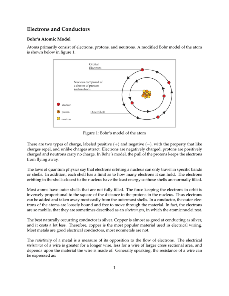
Electrons and Conductors Bohr’s Atomic Model Atoms primarily consist of electrons, protons, and neutrons. A modified Bohr model of the atom is shown below in figure 1. Orbital Electrons e Nucleus composed of a cluster of protons and neutrons e e e e electron proton Outer Shell e neutron Figure 1: Bohr’s model of the atom There are two types of charge, labeled positive (+) and negative (−), with the property that like charges repel, and unlike charges attract. Electrons are negatively charged, protons are positively charged and neutrons carry no charge. In Bohr’s model, the pull of the protons keeps the electrons from flying away. The laws of quantum physics say that electrons orbiting a nucleus can only travel in specific bands or shells. In addition, each shell has a limit as to how many electrons it can hold. The electrons orbiting in the shells closest to the nucleus have the least energy so those shells are normally filled. Most atoms have outer shells that are not fully filled. The force keeping the electrons in orbit is inversely proportional to the square of the distance to the protons in the nucleus. Thus electrons can be added and taken away most easily from the outermost shells. In a conductor, the outer electrons of the atoms are loosely bound and free to move through the material. In fact, the electrons are so mobile, that they are sometimes described as an electron gas, in which the atomic nuclei rest. The best naturally occurring conductor is silver. Copper is almost as good at conducting as silver, and it costs a lot less. Therefore, copper is the most popular material used in electrical wiring. Most metals are good electrical conductors, most nonmetals are not. The resistivity of a metal is a measure of its opposition to the flow of electrons. The electrical resistance of a wire is greater for a longer wire, less for a wire of larger cross sectional area, and depends upon the material the wire is made of. Generally speaking, the resistance of a wire can be expressed as: 1 R= ρL A ρ is the resistivity where L is the length of the conductor A is the cross sectional area of the conductor The factor in the resistance which takes into account the nature of the material is the resistivity. Although it is temperature dependent, it can be used at a given temperature to calculate the resistance of a wire of given geometry. Table 1 gives the relative resistivity of various metals as compared to copper. Resistivity is measured in Ohms (Ω). We will discuss resistance further a few sections from now. Material Silver Gold Aluminum Zinc Brass Iron(pure) Tin Steel Nickel Resistivity Compared to Copper 0.94 1.4 1.6 3.4 3.7-4.9 5.68 6.7 7.6-12.7 12.8 Table 1: Resistivity Compared to Copper Insulators In most solid materials the outermost electrons are so tightly bound that there are no free electrons that can freely move throughout the material. These materials are known as insulators. Typically, the electrons are tightly shared in the orbits of two adjacent atoms. Most compounds of carbon and hydrogen are like this. Plastics, whose molecules are made from long combinations of carbon and hydrogen atoms, have few or no free electrons. This means that plastics make excellent electrical insulators. With enough voltage applied however, any insulating material will eventually succumb to the electrical pressure and electron flow will occur. For voltages below a certain threshold, virtually no electrons will flow, but if the voltage exceeds that threshold, there will be a rush of current. This occurs at what is called the material’s breakdown voltage. Thickness of an insulating material plays a role in determining its breakdown voltage, also known as dielectric strength. Specific dielectric strength is often listed in terms of kilo-volts per inch ( kV in ), but the relationship between breakdown voltage and thickness is not exactly linear. However, for rough estimation use, volt-per-thickness ratings are fine. Below is a table showing the dielectric strength of several common materials. 2 Material Vacuum Air Porcelain Rubber Paper Teflon Glass Mica Dielectric Strength kV /inch 20 20-75 40-200 450-750 1250 1500 2000-3000 5000 Table 2: Dielectric Strength of Various Materials In summary, we keep electrical current flowing where we want it to by use of insulators. Insulation on a electrical wire is like the wall of a water pipe. Semiconductors Materials whose conductance is between conductors and insulators are called semiconductors. To examine this to a greater detail, we will briefly digress into the band theory of materials. The band theory gives us a clear way to distinguish the differences between conductors, semiconductor and insulators. When an atom is in isolation, we speak of its electrons occupying particular discrete energy states. But when a solid consisting of many atoms is formed, the electrons occupy energy bands. The outer most band in an atom is the valence band. But when atoms form a solid, electrons may be elevated into a higher energy level called the conduction band. The determining factor as to whether a material is a conductor, semiconductor or insulator is if there are electrons present in the conduction band. In most materials, the valence band and the conduction band are separated by a wide forbidden zone. Substantial outside energy is required to elevate the valence electrons into the conduction zone. Thus these materials are insulators. In conductors we find that the conduction and valence bands overlap. In semiconductors, the forbidden zone is very small. With such a small gap, a small thermal or electrical excitation can elevate electrons into the conduction zone. Thus with just a little coaxing, the material may change into a conductor or an insulator. Figure 2 below shows how the bands may differ between insulators, semiconductors and conductors. 3 Conduction Band Conduction Band Conduction Band Valence Band Valence Band Valence Band electron energy Insulator The wide energy gap between valence and conduction bands keeps electrons out of the conduction band at ordinary temperatures. Conductor In conductors the conduction band overlaps the valence band so that at ordinary temperatures conduction occurs. Semiconductor In semiconductors, the band gap is small enough that thermal energy can elevate some electrons to the conduction band. Applied electric fields can elevate many electrons to the conduction band. Figure 2: Energy levels in insulators, conductors and semiconductors Semiconductors are relatively poor conductors until they are doped with elements like arsenic, phosphorous or boron. The doping process inserts a small number of doping atoms into the crystal lattice of the original (or bulk) semiconductor. This greatly increases its conductivity by adding an additional level between the original valence and conduction bands. One way doping is applied provides the bulk material with a population of free electrons which have been borrowed or donated by the dopant. The extra available electrons transform the bulk material into a conductor with special properties which allow the fabrication of semiconductor devices such as transistors and diodes. The first transistors and diodes were made with germanium, but making sufficiently pure material was difficult. Now the most commonly used semiconductor is silicon. Other examples of semiconductor materials are Gallium Arsenide (GaAs), Indium Phosphide (InP) and Silicon Germanium (SiGe). Superconductors When cooled to super-low temperatures (near absolute zero, -273°C) conductors lose all of their electrical resistance. Conductors gradually lose resistance as temperature lowers. However, superconductivity occurs with a sudden, quantum leap drop in resistivity from something to nothing. A superconducting material has absolutely zero electrical resistance, not just a small amount. Superconductors are special materials which when cooled below their critical temperature (100K or less) become perfect conductors. The limits of superconductivity not yet been reached, and the 4 theories that explain superconductor behavior are constantly under review. Fully exploited, superconductivity could provide electric circuits that exhibit extraordinary performance. Power losses in electric systems due to resistance could be eliminated. Electric motors could be made nearly 100% efficient. Some superconducting motors, have been developed, but their use is limited due to the problems in maintaining very low temperatures. Critical temperatures for superconductors are generally near absolute zero, but considerable progress has been made in developing high-temperature superconductors; materials which superconduct at warmer temperatures. One type is a ceramic mixture of yttrium, barium, copper, and oxygen which begins to superconduct at 83 degrees Kelvin. Material Aluminum Mercury Tin Niobium/Tin Glass YBCO (Yttrium Barium Copper Oxide) Critical Temperature (K) 1.2 4.6 3.72 18.1 83 Table 3: Critical Temperatures for a Few Substances 5


