Transformer Parameter Extraction
advertisement
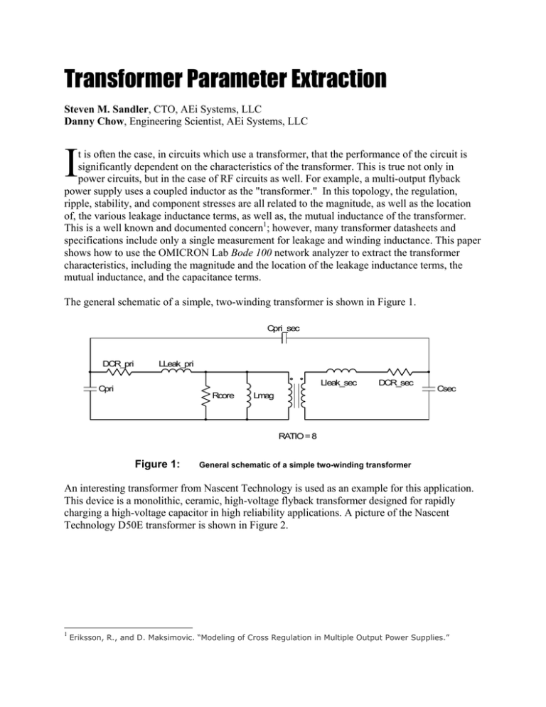
Transformer Parameter Extraction Steven M. Sandler, CTO, AEi Systems, LLC Danny Chow, Engineering Scientist, AEi Systems, LLC I t is often the case, in circuits which use a transformer, that the performance of the circuit is significantly dependent on the characteristics of the transformer. This is true not only in power circuits, but in the case of RF circuits as well. For example, a multi-output flyback power supply uses a coupled inductor as the "transformer." In this topology, the regulation, ripple, stability, and component stresses are all related to the magnitude, as well as the location of, the various leakage inductance terms, as well as, the mutual inductance of the transformer. This is a well known and documented concern1; however, many transformer datasheets and specifications include only a single measurement for leakage and winding inductance. This paper shows how to use the OMICRON Lab Bode 100 network analyzer to extract the transformer characteristics, including the magnitude and the location of the leakage inductance terms, the mutual inductance, and the capacitance terms. The general schematic of a simple, two-winding transformer is shown in Figure 1. Cpri_sec DCR_pri LLeak_pri Lleak_sec Cpri Rcore DCR_sec Lmag Csec RATIO = 8 Figure 1: General schematic of a simple two-winding transformer An interesting transformer from Nascent Technology is used as an example for this application. This device is a monolithic, ceramic, high-voltage flyback transformer designed for rapidly charging a high-voltage capacitor in high reliability applications. A picture of the Nascent Technology D50E transformer is shown in Figure 2. 1 Eriksson, R., and D. Maksimovic. “Modeling of Cross Regulation in Multiple Output Power Supplies.” Figure 2: Nascent Technology Flyback transformer D50E Inductance Terms Each individual transformer winding can be represented by the magnetizing inductance referred to that winding, and the leakage inductance of that winding. Each of the magnetizing inductance terms is related to the permeability of the core and the square of the number of turns of the individual winding. Simple representations of the primary and secondary inductance terms are shown in Figure 3. Lleak_pri 2 V1 Figure 3: Lleak_sec 1 4 AL*Np^2 AL*Nsec^2 3 V2 Inductance representations of the primary and secondary windings The primary inductance, primary DC resistance (DCR), the corresponding core loss resistance (Rcore), and the multiple resonant frequencies of the transformer can be extracted from an impedance measurement of the primary side while the secondary side is open-circuited. Figure 4: Primary impedance measurement when the secondary side is open The 6dB/octave increasing impedance in the mid-band frequencies is the primary referenced inductance, which includes the magnetizing inductance and the primary referenced leakage inductance. The primary inductance, computed from the marker data, is 51.12µH (see calculation below). This inductance and the series DC resistance can also be measured directly, using the impedance/reflection mode of the Bode 100. The frequency sweep mode is preferable, since it provides a visual indication of the resonant frequencies and the inductive portion of the curve with respect to frequency. Z_dB 20 ⋅ log ( 2 ⋅ π ⋅ f ⋅ L ) 1 L( Z_dB , f) := e 20 ⋅ Z_dB ⋅ ln ( 10 ) 2⋅ π ⋅ f −6 L( 24.45, 51120) = 51.967× 10 In order to determine the two individual primary inductance terms (leakage and magnetizing), one additional measurement is needed. Since the turns ratio of the transformer is known, as it is specified in the datasheet to be 1:8, a voltage gain measurement can be made from the primary to the secondary side (see Figure 5 below). As described in Figure 3 above, a voltage divider is formed by the primary referred magnetizing inductance and the primary leakage inductance. Figure 5: Gain of the transformer (Vsec/Vpri) with the secondary side open-circuited 20 ⋅ log ( Gain ) Gain_dB 1 Gain ( Gain_dB ) := e Gain ( 15.967 20 ⋅ Gain_dB ⋅ ln ( 10 ) ) = 6.286 Using the measurements from the impedance measurement and the gain measurement, we can solve for both the primary referred magnetizing inductance and the primary leakage inductance: Ns := := Np 8 Lmag_Pri ⋅ 1 Ns 6.286 Lmag_Pri + Lleak_Pri Np Lmag_Pri Ns ⋅ − 6 Np 52⋅ 10 6.286 Lmag_Pri := 3.2687 × 10 = Lmag_Pri − 4 Np ⋅ × 4.086 −4 Lleak_Pri := 3.2687 × 10 Lleak_Pri = 1.145 Ns 10 ⋅ Lmag_Pri⋅ × 10 − 5 − 5 500.⋅ Ns − 3143.⋅ Np Np Measuring the secondary inductance, which comprises the secondary referred magnetizing inductance and the secondary leakage inductance, allows the determination of the secondary leakage inductance. Since the secondary referred magnetizing inductance is related to the primary magnetizing inductance by the square of the number of turns: 2 := Lmag_Sec ⎛ Ns ⎞ ⋅ Lmag_Pri ⎜ ⎟ ⎝ Np ⎠ = Lmag_Sec × 2.615 − 10 3 Equating the total measured inductance as the sum of this magnetizing inductance and the secondary leakage inductance we get: Lsec_measure + Lleak_Sec Lmag_Sec := Lsec_measure := Lsec_measure Lleak_Sec = Lleak_Sec ⋅ 10 3.15 − 3 − Lmag_Sec × 5.35 10 − 4 All three inductance terms are now defined. An alternate, and simpler, solution is to use the Mathcad “Find” function to solve all three terms simultaneously, based on the extracted measurements. The three inductance terms in the solution are entered as estimated values: Known Values Ns Np := := Guess Values −6 8 1 Lleak_pri := 10⋅ 10 := Lpri_measure 52 ⋅ 10 := Lsec_measure 3.15 ⋅ 10 −6 − 6 Lm := 45⋅ 10 − 3 Lleak_sec := 600⋅ 10 Given Lm Lm + Lleak_pri Lm + ⋅ Ns 6.286 Np Lleak_pri Lpri_measure Lm_sec := Lm ⋅ ⎛⎜ ⎞ ⎟ Np ⎝ ⎠ Lsec_measure Lsec_measure Ns := 2 + Lm_sec := Lm ⋅ ⎛⎜ 2 Lleak_sec ⎞ ⎟ + Lleak_sec ⎝ Np ⎠ Ns −6 ⎛ 4.05 × 10− 5 ⎞ ⎜ ⎟ Find ( Lm, Lleak_pri , Lleak_sec ) = ⎜ 1.104 × 10− 5 ⎟ ⎜ ⎟ ⎜ −4 ⎟ ⎝ 6 × 10 ⎠ Resistance Terms The primary impedance at DC and very low frequency is dominated by the DCR. Figure 4 shows the primary DCR to be 4.8dB or 1.74 Ohms: 4.80 DCR_pri := 10 20 DCR_pri = 1.738 The secondary impedance at DC and very low frequency is also dominated by the DCR. Figure 6 below shows the secondary DCR to be 32.37dB or 41.55 Ohms. These two DCR measurements could also be determined using the impedance/reflection mode of the Bode 100 rather than the frequency sweep mode. Figure 6: Secondary impedance measurement when the primary side is open 32.372 DCR_sec := 10 20 DCR_sec = 41.553 The core loss resistance is obtained as the peak impedance value at the first resonant frequency: Z_dB Z_dB := 73.18 20 ⋅ log ( Rcore ) 1 Rcore := e 20 ⋅ Z_dB ⋅ ln ( 10 ) 3 Rcore = 4.56 × 10 In this measurement, the core loss resistance is approximately 4560Ω. The core loss is both frequency and amplitude dependent; however, we are only extracting the characteristics at one operating condition. The accuracy of this peak value can be improved by increasing the number of data points and reducing the receiver bandwidth of the Bode 100 network analyzer. Capacitance Terms The capacitance terms are obtained from the gain measurements of the transformer. Cpri_sec 0.1p DCR_pri 1.74 7 T1 XFMR RATIO = 8 LLeak_pri 11.15u 9 Rcore 4560 Cpri 20.9p 6 Figure 7: 2 5 Lleak_sec 600u Lmag 40.86u 1 4 DCR_sec 41.55 C_sec 5p 3 Final SPICE transformer model of a two winding flyback transformer Gain (Vsec/Vpri) AEi SIM (Green) / Bench (Pink) 180 60 50 135 40 90 30 0 10 Phase [deg] Magnitude [dB] 45 20 0 -45 -10 -90 -20 -135 -30 -40 1.0E+02 1.0E+03 1.0E+04 1.0E+05 1.0E+06 1.0E+07 -180 1.0E+08 Frequency [Hz] Figure 8: Sim-Bench overlay of the transformer Gain (Vsec/Vpri) (pink: bench measurement, green: simulation result) 20 180 10 135 0 90 -10 45 -20 0 -30 -45 -40 -90 -50 -135 -60 1.0E+02 1.0E+03 1.0E+04 1.0E+05 1.0E+06 1.0E+07 Phase [deg] Magnitude [dB] Gain (Vpri/Vsec) AEi SIM (Green) / Bench (Pink) -180 1.0E+08 Frequency [Hz] Figure 9: Sim-Bench overlay of the transformer Gain (Vpri/Vsec) (pink: bench measurement, green: simulation result) Primary Impedance (Secondary Open) AEi SIM (Green) / Bench (Pink) 100 180 135 80 90 60 40 0 Phase [deg] Magnitude [dB] 45 -45 20 -90 0 -135 -20 1.0E+02 1.0E+03 1.0E+04 1.0E+05 1.0E+06 1.0E+07 -180 1.0E+08 Frequency [Hz] Figure 10: Sim Bench overlay of the primary impedance when the secondary side is open-circuited (pink: bench measurement, green: simulation result) Conclusion The OMICRON Lab Bode 100 allows a complete extraction of the inductance, capacitance, and resistance parameters of the transformer. This allows a wideband SPICE model to be created, which includes both the magnitude and the location of the leakage inductance terms (see Figure 7 above). Comparisons between the bench measurements and simulation results for the transformer gain and primary impedance are shown in Figures 8 – 10 above. Note that the SPICE model is a lumped element model, while the actual transformer is a distributed element. This is the reason for the somewhat limited fidelity of the model at higher frequencies.
