Ideal Operational Amplifiers
advertisement
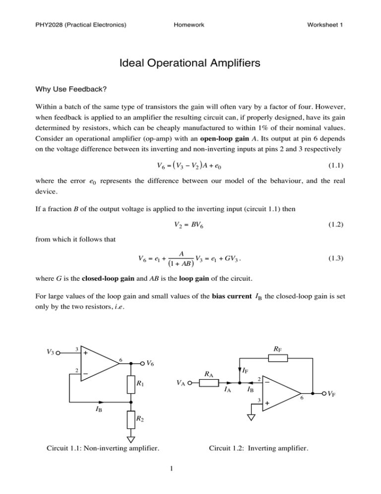
PHY2028 (Practical Electronics) Homework Worksheet 1 Ideal Operational Amplifiers Why Use Feedback? Within a batch of the same type of transistors the gain will often vary by a factor of four. However, when feedback is applied to an amplifier the resulting circuit can, if properly designed, have its gain determined by resistors, which can be cheaply manufactured to within 1% of their nominal values. Consider an operational amplifier (op-amp) with an open-loop gain A. Its output at pin 6 depends on the voltage difference between its inverting and non-inverting inputs at pins 2 and 3 respectively V 6 = ( V3 − V2 ) A + e0 (1.1) where the error e0 represents the difference between our model of the behaviour, and the real device. If a fraction B of the output voltage is applied to the inverting input (circuit 1.1) then V 2 = BV6 (1.2) from which it follows that V 6 = e1 + A V = e + GV3 . (1 + AB ) 3 1 (1.3) where G is the closed-loop gain and AB is the loop gain of the circuit. For large values of the loop gain and small values of the bias current IB the closed-loop gain is set only by the two resistors, i.e. V3 3 RF + 6 2 V6 – IF RA VA R1 IA 2 – 3 + IB 6 IB R2 Circuit 1.1: Non-inverting amplifier. Circuit 1.2: Inverting amplifier. 1 VF PHY2028 (Practical Electronics) Homework G≈ 1 R1 + R2 . = B R2 Worksheet 1 (1.4) An ideal op-amp would therefore have an infinite open-loop gain (guaranteeing AB >> 1) and an infinite input-impedance (guaranteeing IB = 0 ). For such an amplifier to have a finite voltage at its output, the inverting and non-inverting inputs must be equal. The analysis of op-amp circuits is greatly simplified in cases where the ideal op-amp model is an adequate approximation. Application of the Ideal Op-Amp Model The ideal op-amp model, along with Ohm’s and Kirchoff’s Laws can be used to analyse circuit 1.2 as follows: V− = V+ ⇒ V 2 = V 3 = 0V (1.5) IA = (V A − V3 ) RA = VA RA (1.6) IB = 0 and IA + IF + IB = 0 ⇒ IF = − IA (1.7) V F = V 3 + I F RF = −VA RF RA (1.8) Stability It will be shown later in this module that there is an upper limit to how much feedback can be applied to a circuit before it becomes unstable and oscillates. For the 741 op-amp B ≤ 1 is required so it is stable even when 100% feedback is applied. This unity-gain stability requires a compromised the high-frequency performance, so it is the exception rather than the rule. Rx RF Vx Ry Vy 2 – 3 + VF 6 Circuit 1.3: See exercise 1.3 . 2 PHY2028 (Practical Electronics) Homework Worksheet 1 Required Reading Differential Amplifiers – Storey (1998) §3.10 pp. 88–91 / (2006) §3.11 pp. 84–85. Operational Amplifiers – Storey (1998) §3.11 pp. 91–94 / (2006) §5.5 pp. 128–133. Feedback – Storey (1998) §4.1–4.5 pp. 106–126 / (2006) §4.1–4.5 pp. 92–102. Question 1.1 Derive equation 1.3 from equations 1.1 and 1.2 and hence find an expression for e1 in terms of e0 . Answer e1 = e0 (1 + AB) Example 1.2 Equation 1.4 was used to design non-inverting amplifiers of (a) gain 20 and (b) gain 5000. If a 741 op-amp (open-loop gain of about 20,000) were used to build the circuits, what would be the measured gain in each case. Answer (a) Gmeasured = 19.98 (b) Gmeasured = 4000 Example 1.3 Analyse circuit 1.3 using the ideal op-amp model to find (a) V F as a function of V x and V y . Re-analyse the circuit for the case (b) when pin 3 (the non-inverting input) is connected to voltage V z instead of the 0V ground. Answer ( ) (a) V F = − RF V x Rx + V y Ry (b) V F = V z 1+ RF Rx + RF Ry − RF V x Rx + V y Ry ( ) ( ) Example 1.4 What is the (DC) input impedance of (a) circuit 1.1, and (b) circuit 1.2 ? Hint: Imagine connecting a small-voltage source to the input and calculate the current that flows as a result. Answer (a) IB+ = 0 ⇒ Zi n = ∞ (b) V 2 = 0 ⇒ Zi n = RA © Copyright CDH Williams University of Exeter 2012 CW121003/1 1


