About Frequency, Waveforms, Harmonics, and Power
advertisement

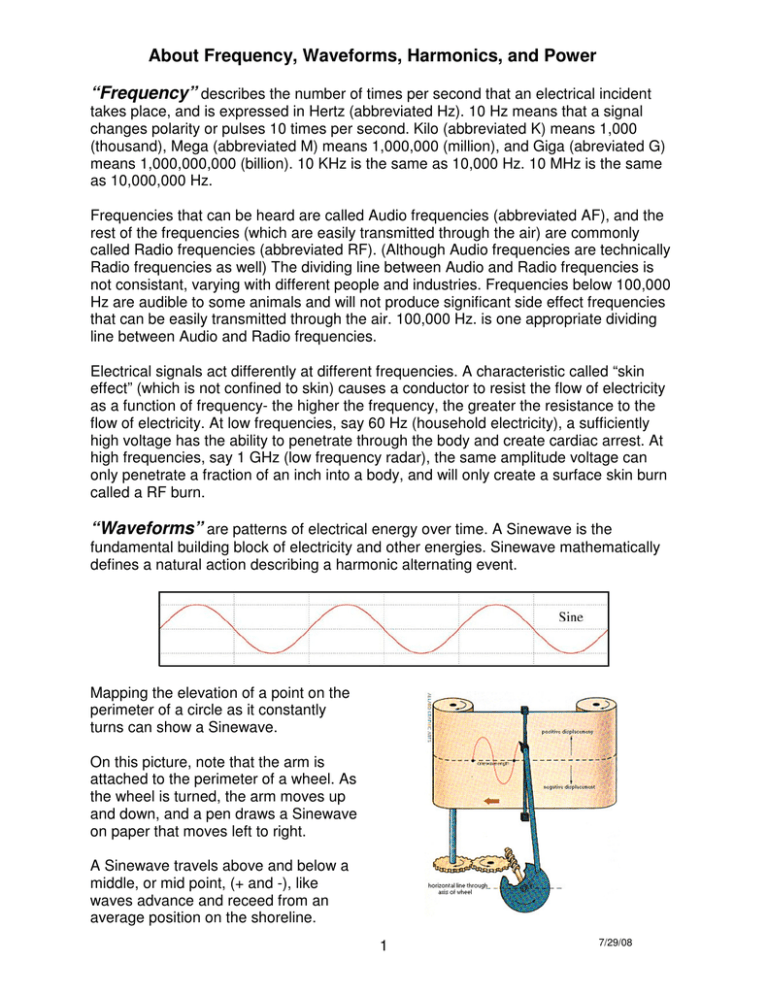
About Frequency, Waveforms, Harmonics, and Power “Frequency” describes the number of times per second that an electrical incident takes place, and is expressed in Hertz (abbreviated Hz). 10 Hz means that a signal changes polarity or pulses 10 times per second. Kilo (abbreviated K) means 1,000 (thousand), Mega (abbreviated M) means 1,000,000 (million), and Giga (abreviated G) means 1,000,000,000 (billion). 10 KHz is the same as 10,000 Hz. 10 MHz is the same as 10,000,000 Hz. Frequencies that can be heard are called Audio frequencies (abbreviated AF), and the rest of the frequencies (which are easily transmitted through the air) are commonly called Radio frequencies (abbreviated RF). (Although Audio frequencies are technically Radio frequencies as well) The dividing line between Audio and Radio frequencies is not consistant, varying with different people and industries. Frequencies below 100,000 Hz are audible to some animals and will not produce significant side effect frequencies that can be easily transmitted through the air. 100,000 Hz. is one appropriate dividing line between Audio and Radio frequencies. Electrical signals act differently at different frequencies. A characteristic called “skin effect” (which is not confined to skin) causes a conductor to resist the flow of electricity as a function of frequency- the higher the frequency, the greater the resistance to the flow of electricity. At low frequencies, say 60 Hz (household electricity), a sufficiently high voltage has the ability to penetrate through the body and create cardiac arrest. At high frequencies, say 1 GHz (low frequency radar), the same amplitude voltage can only penetrate a fraction of an inch into a body, and will only create a surface skin burn called a RF burn. “Waveforms” are patterns of electrical energy over time. A Sinewave is the fundamental building block of electricity and other energies. Sinewave mathematically defines a natural action describing a harmonic alternating event. Mapping the elevation of a point on the perimeter of a circle as it constantly turns can show a Sinewave. On this picture, note that the arm is attached to the perimeter of a wheel. As the wheel is turned, the arm moves up and down, and a pen draws a Sinewave on paper that moves left to right. A Sinewave travels above and below a middle, or mid point, (+ and -), like waves advance and receed from an average position on the shoreline. 1 7/29/08 There are other common waveforms, such as Triangle waves and Square waves: They obviously look different than Sinewaves, but they are closely related. Adding together Sinewaves of different frequencies, amplitudes, and phases creates Triangle, Square, and all other waveforms. The mathematics is straight forward. Here are the frequencies generated by the Ultra: 2 7/29/08 “Harmonics” are all of those Sinewaves of different frequencies that make up a complex waveform, such as Triangle, Square, and all others. Here is a list of “Harmonic Content” of the Power waveforms generated by the Ultra. Harmonic(Multiple) Sinewave Triangle Trapezoid Squarewave Linear Ramp Up Linear Ramp Down Exponential Ramp Up Exponential Ramp Down Hoyland Even Order Harmonics Odd Order Harmonics 1’st (X1) 100% 99% 86% 81% 85% 85% 85% 85% 50% 50% 50% 2’nd (X2) 3’rd (X3) 4’th (X4) 1% 9% 9% 7% 7% 7% 7% 23% 5’th (X5) 3% 3% 2% 2% 2% 2% 9% 6’th (X6) 7’th (X7) 1% 2% 1% 1% 1% 1% 4% 8’th (X8) 9’th (X9) All Others 1% 1% 1% 1% 1% 1% 3% 4% 4% 4% 4% 4% 11% 50% 50% (Numbers shown are Power, not Waveform Amplitude. Power is the product of voltage and current, and is what is delivered.) The “1’st” Harmonic is the actual fundamental frequency itself. The “2’nd” Harmonic is a frequency that is twice as large as the fundamental frequency. The “3’rd” Harmonic is a frequency that is 3 times as large as the fundamental frequency, and so on. Example: For a Frequency of 100 Hz, the 2’nd Harmonic is 200 Hz; the 3’rd Harmonic is 300 Hz. A 100 Hz Triangle waveform is created by adding together 99% of a 100 Hz Sinewave with 1% of a 300 Hz Sinewave. Phase describes the relationship of the starting points of each Harmonic in time. Different phases will result in different looking waveforms, but will not change the amounts or ratios of power delivered for each Harmonic. “Power” Different Waveforms are created with equal Peak to Peak values (lowest point to the highest point). However, equal Peak to Peak values does not translate to equal power delivered. Different waveforms (with equal Peak to Peak values) deliver different amounts of power. This table shows the relative power of different waveforms. Squarewave Trapezoid Exponential Ramp Down Sinewave Odd Order Harmonics Linear Ramp Up Linear Ramp Down Triangle Even Order Harmonics Exponential Ramp Up Hoyland 100% 94% 53% 50% 42% 34% 33% 33% 32% 20% 11% In other words, at equal intensity settings, a Squarewave will deliver 3 times more power than a Triangle Wave. Or, using a Squarewave with the intensity setting at 33% delivers the same amount of power as using a Triangle wave with the intensity set at 100%. 3 7/29/08 The Ultra: The Ultra is capable of generating 3 simultanous “Arbitrary” waveforms. Arbitrary waveforms are computer generated and are not restricted to electronic signals, such as Sine and Squarewave. Because the waveforms are arbitrary, any combination of Harmonics in any ratio and phase is possible. Any Arbitrary waveform can be used for each of the 3 Ultra waveforms. 1. “Gate” or “Pulse” is the terms used for the first Ultra waveform. These terms are used because they are common to this industry, but the Ultra has much greater capability in this area, and the correct term should be “Modulate”. Modulating the waveform increases and decreases the intensity of the Output following the pattern of the selected Arbitrary waveform. Common Gating or Pulsing cannot do this- it can only turn the signal on and off. For a Gate or Pulse waveform to adequately pass the harmonics of the Output, the Gate or Pulse frequency should be lower than the rest of the waveform frequencies. Programming a “Duty Cycle” will insert an Off time in between each Modulated waveform and will correspondingly alter the frequency of the waveform. Example: A frequency of 1 Hz. is selected, which is 1 change per second. A duty cycle of 50% is selected. One complete waveform will take place in ½ second, after which the output will be blanked for ½ second. The process will then repeat. Selecting a Duty Cycle of 100% prevents any Modulation of the output, leaving it on full the entire time. 2. “Carrier” is the term for the second Ultra waveform, and following conventional electronics, it “carries” a lower frequency within it. As such, in order to work properly, a Carrier frequency should be higher than the remaining waveform frequency. 3. “Frequency” is the term for the last Ultra waveform and is “carried” by the Carrier. Sequences are generally composed of a program of “Frequencies” one after another, each with the same “Gate” or “Pulse”, and “Carrier” (which is optional). “Pulsewidth”: In addition to the waveforms described, there is an additional Arbitrary waveform that operates differently. It is called “Pulsewidth”. Pulsewidth varies the On to Off ratio in a sweeping pattern as the program runs. Example: A frequency of 1 Hz is selected, which is 1 change each second. The Output is turned on for 1/100’th of a second, and then turned off for 99/100’ths of a second. Next, it is turned on for 2/100’ths of a second, and then off for 98/100’ths of a second. This continues until it is on 99/100’ths of a second, after which the sweep starts again. Electrodes are “differential”. Each operates at a different polarity than the other, and they change polarities with frequency- when one is +, the other is -. All 3 waveforms can be applied to Electrodes. Raytubes also have polarity, but the Carrier is fixed at 45 kHz. Any Carrier frequencies entered in the Ultra when using Raytubes only apply to Electrodes. LED Wand has no polarity, and all 3 waveforms can be applied to it. 4 7/29/08


