1 Thermodynamics and Heat Transfer ECE 309 Tutorial # 4 First
advertisement
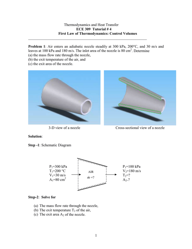
Thermodynamics and Heat Transfer ECE 309 Tutorial # 4 First Law of Thermodynamics: Control Volumes _______________________________________________________________ Problem 1: Air enters an adiabatic nozzle steadily at 300 kPa, 200°C, and 30 m/s and leaves at 100 kPa and 180 m/s. The inlet area of the nozzle is 80 cm2. Determine (a) the mass flow rate through the nozzle, (b) the exit temperature of the air, and (c) the exit area of the nozzle. 3-D view of a nozzle Cross-sectional view of a nozzle Solution: Step -1: Schematic Diagram P1=300 kPa T1=200 °C V1=30 m/s A1=80 cm2 P1=100 kPa V2=180 m/s T2=? A2=? AIR m& =? Step-2: Solve for (a) The mass flow rate through the nozzle, (b) The exit temperature T2 of the air, (c) The exit area A2 of the nozzle. 1 Step-3: Make table of values for the substance or fluid given Initial Condition Final Condition Pressure (kPa) 300 100 Temperature (K) 200+273=473 Unknown Area (m2) 0.008 Unknown Velocity (m/s) 30 180 Step-4: Analysis The region within the nozzle is selected as the system, and its boundaries are indicated by the dashed lines in the schematic diagram. Mass is crossing the boundaries, thus it is a control volume. And since there is no observable change within the control volume with time, it is a steady-flow system. As the specified conditions, the air can be treated as an ideal gas since it is at a high temperature and low pressure relative to its critical values (Tcr= – 147 °C and Pcr=3390 kPa for nitrogen, the main constituent of air). (a) To determine the mass flow rate, we need to find the specific volume of the air first. This is determined from the ideal-gas relation at the inlet conditions: Specific volume at inlet: υ1 = Mass flow rate: m& = 1 υ1 ( RT1 0.287 kPa ⋅ m 3 /kg ⋅ K = P1 300 kPa A1V1 = ( 1 0.008 m 2 3 0.4525 m /kg ) (473 K ) = 0.4525 m /kg 3 ) (30 m/s ) = 0.5304 kg/s Since the flow is steady, the mass flow rate through the entire nozzle will remain constant at this value. (b) A nozzle normally involves (i) no shaft or electrical work (w=0), (ii) negligible heat transfer (q ≈ 0), and (iii) a small (if any) elevation change between the inlet and exit ( ∆ pe ≈ o). Then the conservation of energy relation on a unit mass basis for this single-stream steady-flow system reduces to q − w = ∆h + ∆ke + ∆pe 0 − 0 = ∆h + ∆ke + 0 V − V1 0 = h2 − h1 + 2 2 2 0 = C p (T2 − T1) + 2 2 V22 − V12 2 Using specific heats at the anticipated average temperature of 450K (Cp=1.020 kJ/kg⋅K, Cv=0.733 kJ/kg⋅K, and R=Cp–Cv=0.287 kJ/kg⋅K; see Table A-2), the exit temperature of air is determined to be T2 = T1 − V 22 − V12 180 2 m 2 /s 2 − 30 2 m 2 /s 2 = 200 o C − 2C p 2 × (1020 J/kg ⋅ o C ) = 200 C − o 180 2 m 2 /s 2 − 30 2 m 2 /s 2 2 × (1020 m /s ⋅ C ) 2 2 o = 184.6 o C kg ⋅ m m J N⋅m m2 Note :1 =1 =1 2 =1 2 kg kg kg s s This shows that the temperature of the air is decreased by about 15°C. The temperature drop of the air is mainly due to the conversion of internal energy to the kinetic energy. (c) To determine the exit area, we need to find the specific volume of the exit air from the ideal- gas relation. ( ) RT2 0.287 kPa ⋅ m 3 /kg ⋅ K (184.6 + 273)K υ2 = = = 1.313 m 3 /kg P2 100 kPa Since the mass flow rate of the air is constant, exit area can be found from the mass flow rate equation. m& = 1 υ2 A2V 2 → 0.5304 kg/s = 1 A2 (180 m/s ) 1.313 m 3 /kg A2 = 0.00387 m 2 = 38.7 cm 2 3 Problem2: A hair dryer is basically a duct in which a few layers of electric resistors are placed. A small fan pulls the air in and forces it through the resistors where it is heated. Air enters a 1200 watt hair dryer at 100 kPa and 22°C and leaves at 47°C. The crosssectional area of the hair dryer at the exit is 60cm2. The power consumed by the fan is 2 watt and the heat losses through the walls of the hair dryer is 5 watt, determine (a) the volume flow rate of the air at inlet (b) the velocity of the air at the exit 3-D view of hair dryer Cross-section of hair dryer showing heating element and fan Solution: Step -1: Schematic Diagram Fan Heating element Q = -5 watt P2=? T2=47°C υ2=? A2=60cm2 P1=100 kPa T1=22°C υ1=? A1=? Wf = -2 watt Wh = -1200 watt Step-2: Solve for & (a) the volume flow rate of the air at inlet, ∀ in (b) the velocity of air at the exit, V2 4 Step-3: Make table of values for the substance or fluid given Pressure (kPa) 100 ? Inlet condition Exit condition Temperature (K) 22+273=295 47+273=320 Area (m2) ? 0.006 Velocity (m/s) ? ? Step-4: Analysis The region within the hair dryer is selected as the system, and its boundaries are indicated by the dashed lines in the schematic diagram. Mass is crossing the boundaries, thus it is a control volume. And since there is no observable change within the control volume with time, it is a steady-flow system. As the specified conditions, the air can be treated as an ideal gas since it is at a high temperature and low pressure relative to its critical values (Tcr= – 147 °C and Pcr=3390 kPa for nitrogen, the main constituent of air). (a) The conservation of energy relation in the rate form for this single-stream steadyflow system is Q& − W& = m& [∆h + ∆KE + ∆PE ] V22 − V12 & & + g ( z 2 − z1 ) ⇒ Q − W = m& (h2 − h1 ) + 2 Assumptions: (a) fixed elevation; that is, negligible potential energy (∆PE≈0) (b) change in kinetic energy is small (∆KE≈0) (c) inlet and exit sections of the hair dryer are exposed to atmosphere; that is, P1=P2 Therefore, the reduced form of the energy equation is Q& − W& = m& (h − h ) = m& C (T − T ) 2 1 p 2 1 ⇒ ( −5 watt ) − ( −1200 watt − 2 watt ) = m& (1.005 kJ/kg ⋅ K ) ( 320 K − 295 K ) 1197 watt 1197 J/s ⇒ m& = = = 0.047641 kg/s (1.005 kJ/kg ⋅ K ) ( 25 K ) (1005 J/kg ⋅ K ) ( 25 K ) Note: In the above calculation specific heats are calculated at the anticipated average temperature of 300K (Cp=1.005 kJ/kg⋅K, Cv=0.718 kJ/kg⋅K, and R=Cp–Cv=0.287 kJ/kg⋅K; see Table A-2). 5 Now, using the equation of state: Pυ = RT ( ) RT1 0.287 kPa ⋅ m 3 /kg ⋅ K ( 295 K ) Specific volume at inlet: υ 1 = = = 0.84665 m 3 /kg 100 kPa P1 Using the mass conservation equation Mass flow rate: m& = ρ 1 V1 A1 = V1 A1 υ1 = & ∀ 1 υ1 & is the volume flow rate at inlet. where, ∀ 1 & = υ m& = ( 0.84665 m 3 /kg) ( 0.047641 kg/s) = 0.04033 m 3 /s Volume flow rate in inlet: ∀ 1 1 (b) mass flow rate must be constant at the inlet and outlet, therefore m& = ρ 2 V 2 A2 = V 2 A2 υ2 ⇒ V2 = m& υ 2 A2 The only unknown in above equation is υ2 and it is calculated from υ2 = ( ) RT2 0.287 kPa ⋅ m 3 /kg ⋅ K (320 K ) = = 0.9184 m 3 /kg 100 kPa P2 Now the velocity at the exit is V2 = m& υ 2 ( 0.047641 kg/s) (0.9184 m 3 /kg) = = 7.2922 m/s A2 ( 0.006 m 2 ) 6
