Kirchhoff`s Laws
advertisement
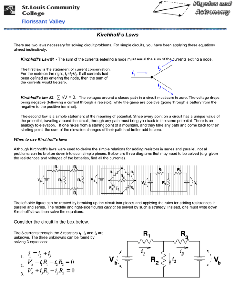
Kirchhoff’s Laws There are two laws necessary for solving circuit problems. For simple circuits, you have been applying these equations almost instinctively. Kirchhoff's Law #1 - The sum of the currents entering a node must equal the sum of the currents exiting a node. The first law is the statement of current conservation. For the node on the right, i1=i2+i3. If all currents had been defined as entering the node, then the sum of the currents would be zero. Kirchhoff's law #2 V = 0. The voltages around a closed path in a circuit must sum to zero. The voltage drops being negative (following a current through a resistor), while the gains are positive (going through a battery from the negative to the positive terminal). The second law is a simple statement of the meaning of potential. Since every point on a circuit has a unique value of the potential, traveling around the circuit, through any path must bring you back to the same potential. There is an analogy to elevation. If one hikes from a starting point of a mountain, and they take any path and come back to their starting point, the sum of the elevation changes of their path had better add to zero. When to use Kirchhoff's laws Although Kirchhoff's laws were used to derive the simple relations for adding resistors in series and parallel, not all problems can be broken down into such simple pieces. Below are three diagrams that may need to be solved (e.g. given the resistances and voltages of the batteries, find all the currents). The left-side figure can be treated by breaking up the circuit into pieces and applying the rules for adding resistances in parallel and series. The middle and right-side figures cannot be solved by such a strategy. Instead, one must write down Kirchhoff's laws then solve the equations. Consider the circuit in the box below. The 3 currents through the 3 resistors i1, i2 and i3 are unknown. The three unknowns can be found by solving 3 equations: 1. 2. 3. 1. The first equation describes current conservation into the node. Note that i1 is defined as flowing into the node (to the right) while i2 and i3 are defined as flowing out of the node (down and to the right). 2. The second equation expresses the requirement that voltage losses cancel voltage gains for the loop on the left. This loop was traversed clockwise. 3. The third equation expresses the sum of voltages around the right loop. Note that if one makes a counterclockwise loop, one goes against the current through R3 and the sign of that term is therefore opposite the normal one. Remember that one gains the voltage of the battery when traveling from the small hashes and leaving from the large hashes in the battery. One could also imagine writing equations for a third loop, which travels all the way around the circuit, through both batteries. However, such an equation is merely a linear combination of Eq. 2 and Eq. 3 above. We do an example like this below. Example Problem Find the currents through all the resistors in the circuit below: DATA: Vb = 12 V, R1 = 10 , R2 = 15 , R3 = 20 Solution: Summing the voltages clockwise around the left and right loops gives the following two equations: 1. left loop: Vb - i1R1 – i2R2 = 0 2. right loop: -Vb + i2R2 – i3R3 = 0 Summing the currents in the top node we get: i1 – i2 – i3 = 0 i3 = i1 – i2 or We can plug this value for i3 into equation 2 above to get: 2. Vb = i2R2 – (i1 – i2 )R3 Multiplying Eq. (1) by R3, multiplying Eq. (2) by R1, then adding the equations yields: Which rearranged yields Once i2 is known, Eq. (1) can be used to get i1, and i3 can be found as the difference i1 - i2. i2 = 0.554 amps, i1= .369 amps, i3 = -.185 amps KIRCHHOFF'S LAWS LAB PURPOSE: To verify Kirchhoff’s laws by comparing the currents found by using Kirchhoff’s laws with those experimentally found using a real circuit and a digital multimeter. METHOD: Apply Kirchhoff's Laws to the DC circuit shown below and solve for the currents in the network. Then, physically assemble the circuit with the power supply and resistors provided. Finally compare the experimental to the theoretical results. APPARATUS: Kirchhoff's law circuit board Digital Multimeter PROCEDURE: 1. Look at the following diagram. This is the circuit you will be building. R1 = 100 R2 = 50 R3 = 25 R4 = 20 R5 = 30 R6 = 75 1 = 12 V 2 = 10 V 3= 8V Now build the actual circuit to get your experimental results. 1. Connect the circuit as shown in Figure 2. BEFORE TURNING ON ANY POWER SUPPLY HAVE AN INSTRUCTOR CHECK YOUR WIRING! 2. Turn on each of the power supplies. 3. Connect the voltmeter to the first power supply and adjust the voltage to 12.0 Volts. Record this value on your data sheet. In turn, adjust 2 to 10.0 Volts and 3 to 8.0 Volts. Record all voltages. 4. Put the ammeter in series with R1 to measure the current in this branch. To do this, disconnect one lead from R1. Connect the ammeter between this lead and the terminal this lead was connected to. Record this current (I1) along with the observed current direction, disconnect the ammeter and reconnect the lead as it was before the current was measured. (Ask for help if you are not sure how to use the multimeter) 5. Measure and record I2, I3, I4 and I5 along with the observed current direction in the same way. 6. Turn all power supply voltages to zero, and then turn them off. Turn off the multimeter, and disconnect the circuit wiring before you leave the lab station. KIRCHHOFF'S LAWS LAB Sheet 1 DATA TABLE: Voltage E1 E2 E3 Experimental Current I1 I2 I3 CALCULATIONS: SHOW ALL WORK 1. Label the currents, label the junctions and show the chosen loops. Set up the Kirchhoff's Law equations for the circuit. Be sure to label the current through R1 as I1, the current through R2 as I2, the current through R3 as I3, the current through R4 as I4 and the current through R5 as I5. 2. Solve your equations for the currents, I1 through I5 using Solving Simultaneous Equations excel program on lab computers in SM252. PRINT ONLY 1 PAGE 3. Calculate the percent error between the experimental value and actual value of current. RESULT TABLE: Actual Current I1 CONCLUSION: I2 I3 I4 I5 Percent Error I4 I5 TURN IN: LAB SHEET 1, SOLVING SIMULTANEOUS PRINT OUT
