Multiloop Circuits
advertisement
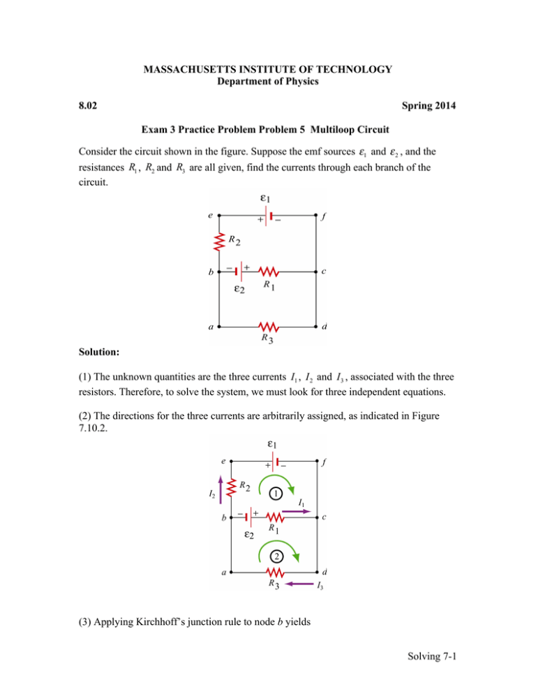
MASSACHUSETTS INSTITUTE OF TECHNOLOGY Department of Physics 8.02 Spring 2014 Exam 3 Practice Problem Problem 5 Multiloop Circuit Consider the circuit shown in the figure. Suppose the emf sources ε1 and ε 2 , and the resistances R1 , R2 and R3 are all given, find the currents through each branch of the circuit. Solution: (1) The unknown quantities are the three currents I1 , I 2 and I 3 , associated with the three resistors. Therefore, to solve the system, we must look for three independent equations. (2) The directions for the three currents are arbitrarily assigned, as indicated in Figure 7.10.2. (3) Applying Kirchhoff’s junction rule to node b yields Solving 7-1 I1 + I 2 = I 3 , because I1 and I 2 are leaving the node while I 3 is entering the node. The same equation is obtained if we consider node c. (4) The other two equations can be obtained by using the loop rule, which states that the sum of the potential difference across all elements in a closed circuit loop is zero. Traversing the first loop befcb in the clockwise direction yields − I 2 R2 − ε1 + I1 R1 − ε 2 = 0 . Similarly, traversing the second loop abcda clockwise gives ε 2 − I1 R1 − I 3 R3 = 0 . Note however, that one may also consider the big loop abefcda. This leads to − I 2 R2 − ε1 − I 3 R3 = 0 . However, the equation is not linearly independent of the other two loop equations since it is simply the sum of those equations. (5) The solutions to the above three equations are given by, after tedious but straightforward algebra, I1 = ε1 R3 + ε 2 R3 + ε 2 R2 , R1 R2 + R1 R3 + R2 R3 I2 = − I3 = ε1 R1 + ε1 R3 + ε 2 R3 , R1 R2 + R1 R3 + R2 R3 ε 2 R2 − ε1 R1 . R1 R2 + R1 R3 + R2 R3 Note that I2 is a negative quantity. This simply indicates that the direction of I2 is opposite of what we have initially assumed. Solving 7-2
