The ideal transformer with two secondary windings

The ideal transformer with two secondary windings
This paper extends the analysis in the paper titled The ideal transformer with a single secondary winding .
The notation and results of the earlier paper are used below without a lot of explanation.
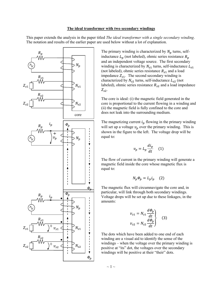
The primary winding is characterized by turns, selfinductance (not labeled), ohmic series resistance core and an independent voltage source. The first secondary winding is characterized by turns, self-inductance
(not labeled), ohmic series resistance and a load impedance . The second secondary winding is characterized by turns, self-inductance (not labeled), ohmic series resistance and a load impedance
.
The core is ideal: (i) the magnetic field generated in the core is proportional to the current flowing in a winding and
(ii) the magnetic field is fully confined to the core and does not leak into the surrounding medium.
The magnetizing current flowing in the primary winding will set up a voltage over the primary winding. This is shown in the figure to the left. The voltage drop will be equal to:
The flow of current in the primary winding will generate a magnetic field inside the core whose magnetic flux is equal to:
The magnetic flux will circumnavigate the core and, in particular, will link through both secondary windings.
Voltage drops will be set up due to these linkages, in the amounts:
The dots which have been added to one end of each winding are a visual aid to identify the sense of the windings – when the voltage over the primary winding is positive at “its” dot, the voltages over the secondary windings will be positive at their “their” dots.
~ 1 ~
In response to the voltages drops over the secondary windings, currents and will flow through the secondary circuits. The circuit equations of the secondary circuits will be governed by Ohm’s Law or its equivalents for the appropriate impedances:
The currents and flowing through the secondary windings will generate their own magnetic fluxes, in amounts given by:
Perhaps a better way to say this is that magnetic fluxes and “drain” the magnetic field generated by the primary winding. The currents use up the energy drained from the primary’s magnetic field. In this sense, and
represent energy lost from the primary circuit.
Indeed, the primary circuit must supply the additional energy. The voltage source does this by allowing more current, in the additional amount of , to flow through the primary winding, as shown in the figure to the left. In order to generate the additional flux, , the additional current must be equal to:
We are now in a position to bring together the expressions we have to find the equation we want, namely, an equation for the currents flowing in the primary circuit or, alternatively, an equation between the voltage over the
(ideal) primary winding and the total current flowing through the primary winding. The total current flowing through the primary winding is equal to:
~ 2 ~
Substituting Equation into Equation gives:
Substituting Equation gives:
Substituting Equation gives:
In general, the impedances and are not solely resistive, but will be integral and differential operators. We can “divide through” only if we bear this in mind and properly account (as we do below) for doing so. Now, substituting Equation gives:
Substituting Equation gives:
Substituting Equation gives:
There are three terms in Equation , which tells us that the total current flowing in the primary circuit can be modeled as a parallel circuit with three branches, as shown in the following figure.
~ 3 ~
First branch
The first branch is the self-inductance of the primary winding. The current flowing through this branch is the magnetizing current.
Second banch
Consider the middle term on the right-hand side of Equation . This is the term which represents the first secondary winding. The term is a current, for which we will use the symbol , where the subscripts identify this current as the current flowing in the primary circuit as a result of activity in the secondary circuit. Then:
This can be re-arranged into the form of Ohm’s Law, which gives:
That the two voltages on the right-hand side of Equation are added together indicates that this is a series combination of two components. The first component is a resistance whose magnitude is the ohmic resistance of the first secondary circuit, transformed by the ratio of the inductance in the primary winding to the inductance in the first secondary winding. The second component is a similar transformation of the load impedance in the first secondary circuit.
Third branch
Similarly, the second secondary circuit is characterized by:
Typical impedance operators
In Equations and , the impedance operators and are back in the numerator, signifying that the division above has been undone. They can now “operate” on the currents and , respectively. As an example, consider the case where the load of the first secondary circuit is a series combination of resistor , capacitor and inductor . The operation would be expanded as:
~ 4 ~
The ratio of self-inductances and the turns ratio
Using the same procedure as described in the earlier paper, it can be shown that the ratio of selfinductances between any two windings is the same as the ratio of their numbers of turns.
Jim Hawley
October 2011
An e-mail describing errors and omissions would be appreciated.
~ 5 ~

![FORM NO. 157 [See rule 331] COMPANIES ACT. 1956 Members](http://s3.studylib.net/store/data/008659599_1-2c9a22f370f2c285423bce1fc3cf3305-300x300.png)