wireless microphone setup
advertisement

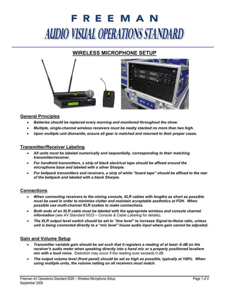
WIRELESS MICROPHONE SETUP General Principles • Batteries should be replaced every morning and monitored throughout the show. • Multiple, single-channel wireless receivers must be neatly stacked no more than two high. • Upon multiple unit dismantle, ensure all gear is matched and returned to their proper cases. Transmitter/Receiver Labeling • All units must be labeled numerically and sequentially, corresponding to their matching transmitter/receiver. • For handheld transmitters, a strip of black electrical tape should be affixed around the microphone base and labeled with a silver Sharpie. • For beltpack transmitters and receivers, a strip of white “board tape” should be affixed to the rear of the beltpack and labeled with a black Sharpie. Connections • When connecting receivers to the mixing console, XLR cables with lengths as short as possible must be used in order to minimize clutter and maintain acceptable aesthetics at FOH. When possible use multi-channel XLR snakes to make connections. • Both ends of an XLR cable must be labeled with the appropriate wireless and console channel information (see AV Standard 0023 – Console & Cable Labeling for details). • The XLR output level switch should be set to “line level” to increase Signal-to-Noise ratio, unless unit is being connected directly to a “mic level” house audio input where gain cannot be adjusted. Gain and Volume Setup • Transmitter variable gain should be set such that it registers a reading of at least -6 dB on the receiver’s audio meter when speaking directly into a hand mic or a properly positioned lavaliere mic with a loud voice. Distortion may occur if the reading ever exceeds 0 dB. • The output volume level (front panel) should be set as high as possible, typically at 100%. When using multiple units, the volume setting on all receivers must match. Freeman AV Operations Standard 0026 – Wireless Microphone Setup September 2008 Page 1 of 2 Antennas • ½-Wave Whip Antennas o The frequency band of each antenna must be checked that it matches the frequency band of its corresponding receiver and transmitter prior to installation. o Whip antenna must be attached to the rear of the receiver at a 45º-angle below vertical (see picture, right). o On multi-channel wireless racks with front panel BNC connectors, attach the whip antenna to the front panel at a 45º-angle below vertical. • • NOTE: Rack antenna connections must be checked for proper connection from the antenna distribution system to receivers. Paddle (Log Periodic) Antennas o The frequency range of each paddle antenna must be checked that it is compatible with the frequency band of the corresponding wireless system being used prior to installation. o Paddle antennas should be mounted to a microphone stand and placed above head level (higher than 6 feet). As paddle antennas are highly directional, the “tip” of both antennas must point toward the expected location of the transmitters. Paddle antennas may be connected directly to a receiver, or to an antenna distribution system. • NOTE: Rack antenna connections must be checked for proper connection from the antenna distribution system to receivers. Paddle antennas should only be connected using the included 25’ 50Ω BNC cables. • NOTE: Video BNC cables have an impedance of 75Ω and will result in signal degradation due to the impedance mismatch. 75Ω video BNC cables must never be used unless there is no other option. Frequency Selection • The frequency bands of every transmitter must be checked that it matches the frequency band of its corresponding receiver prior to installation. A transmitter in one frequency band (i.e. L3) cannot be used with a receiver in a different frequency band (i.e. J5). • Pre-programmed frequency groups and channels should be used at all times. • When using multiple wireless units in the same room/area, frequencies must be coordinated so that no channels are accidently repeated. • In order to avoid TV broadcast and other RF interference, especially when using/competing with multiple units, the Shure Wireless Frequency Finder chart should be consulted, located at: http://www.shure.com/ProAudio/TechLibrary/WirelessFrequencyFinder/index.htm. Microphone Placement • See AV Standard 0016 – Microphone Placement for detailed mic technique information. • Beltpacks (and specifically antennas) must be allowed to dangle freely for maximum RF transmission distance and cannot be allowed to be coiled or stuffed inside a pocket. Freeman AV Operations Standard 0026 – Wireless Microphone Setup September 2008 Page 2 of 2

![EEE 443 Antennas for Wireless Communications (3) [S]](http://s3.studylib.net/store/data/008888255_1-6e942a081653d05c33fa53deefb4441a-300x300.png)
