led flasher - ABRA Electronics
advertisement

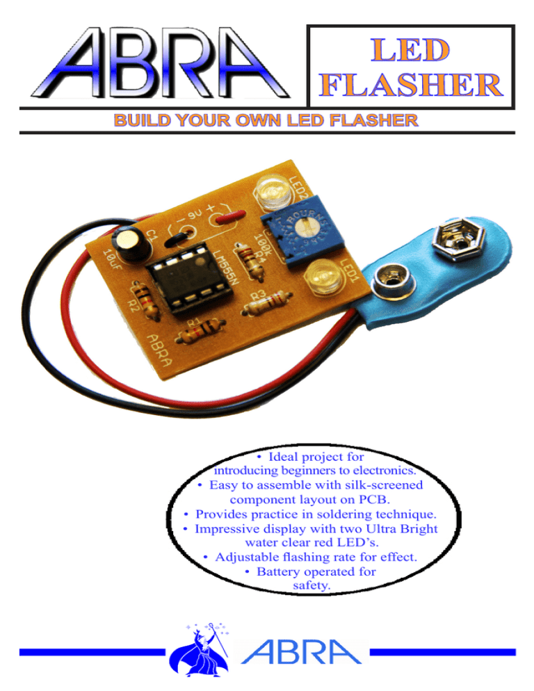
LED FLASHER BUILD YOUR OWN LED FLASHER • Ideal project for introducing beginners to electronics. • Easy to assemble with silk-screened component layout on PCB. • Provides practice in soldering technique. • Impressive display with two Ultra Bright water clear red LED’s. • Adjustable flashing rate for effect. • Battery operated for safety. Tools Required: •Soldering Iron •Solder •Diagonal Cutters •9V Battery Kit Description: The LED FLASHER KIT alternately flashes two red LEDs. The flashing rate can be adjusted by varying the resistance of the P1 potentiometer. Timing is provided by the popular 555 integrated circuit. The 555 timer produces square wave pulses with a frequency that is determined by the combination of the R1, R2, P1 and C1 values. Circuit Description: The circuit is composed of a 555 timer IC which creates square pulses, alternating between a HIGH and LOW state at pin3. The pulses flash LED1 and LED2. The frequency of the square pulses are controlled by a time constant determined by the C1 capacitor, the R1, R2 resistors and the resistance of the P1 potentiometer. General Assembly Guidelines: Good soldering technique is the most important factor in successfully assembling your kit. A small pencil type soldering iron 25-40 Watts is recommended. The tip of the iron should be kept clean at all times by wiping it often on damp sponge or cloth. Touch the component lead and the solder pad junction with the soldering iron tip. Apply solder to the junction. It should not take more than 1-2 seconds for the solder to melt. A good solder joint will appear shiny and conform to the lead. Refer to the ABRA website at www.abra-electronics.com using the part number if you cannot identify a part in the part list. Parts list: Item ABRA Part# IC1 LM555 SOCKET 8LP LED1,LED2 LED-5CR R1, R2 R1/4-10k R3, R4 R1/4-220 P1 3386P-1-104 C1 10R16 9V CLIP 29-130 PCB LED-Blinky-B Description Quantity Single Timer IC 1 Dip Socket for LM555 Timer IC 1 Clear Red Diffused LED 2 10k Ohm Resistor (Brown, Black, Orange) 2 220 Ohm Resistor (Red, Red, Brown) 2 100k Ohm Potentiometer 1 10uF Polarized Capacitor 1 9V Battery Clip 1 LED Flasher Kit PCB 1 PCB Layout Schematics Assembly step by step: 1. Install Resistors R1, R2, R3 and R4 as shown in the PCB Board Layout using their color codes to identify them. The leads can go in either way. Solder the resistors in place and trim the leads with the diagonal cutters. 2. Install Capacitor C1 as shown on the PCB Layout. C1 is a polarized capacitor and must be placed with its shorter lead, indicating the negative side in the hole marked with a minus sign. The white line on the side of the capacitor also indicates the negative side. Solder C1 in place and trim the leads 3. Install the Potentiometer P1 as shown. Solder P1 in place and trim the leads. 4. Install LED1 and LED2 with their short lead in the hole with the minus sign. The short lead is the cathode side. Solder the LEDs in place and trim the leads. 5. Install the socket for the LM555 timer IC with the small notch as shown in the PCB Board Layout. Solder the socket pins in place. Install the LM555 timer on the dip socket with the notches on the LM555 and the socket on the same side. 6. To install the 9V battery clip, first pass the wires from the bottom side through the holes adjacent to the battery solder pads and then into the solder pads. Connect the red wire to the + and the black wire to the – connection on the board Solder the wires in place. 7. Before connecting the battery to the circuit, review your work as per the Assembly Check out. Assembly Check out: • It is highly recommended to inspect the PCB carefully. • Check for proper placement of components. • Check that capacitor C1, IC1, & both LEDs are installed in the correct direction. • Check that all connections are soldered with a shiny appearance. • Redo any solder connection that is dull looking or in a ball. • Check that there are no solder bridges touching adjacent connections together. Solder Profiles: Operation: Connect the 9 Volt battery to the battery clip. With a small flat screwdriver adjust the potentiometer until you can see both LED lights flash alternatively. You can vary both LED’s alternately flashing rate or have just one LED constantly on. Troubleshooting: • Turn the potentiometer w/ a small screwdriver to see both LED flash alternately. • If one of the LEDs do not light up then probably its polarity was reversed. • Unsolder the LED and solder it the other way around. • Verify that the 555 timer IC was installed with its notch facing down as per the PCB Board Layout. • Verify if that the resistors values are correctly placed. • The R1 and R2 resistors should be 10k. • Verify that C1 capacitor polarity is correct. • Replace the 9V battery if the circuit has been functioning and then stops. www.abra-electronics.com U.S Toll Free: 1-800-717-2272 sales@abra-electronics.com Can.Toll Free: 1-800-361-5237 MADE IN CANADA


