X. Faraday`s Law - Worked Examples
advertisement

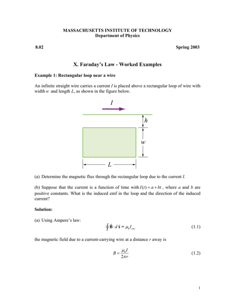
MASSACHUSETTS INSTITUTE OF TECHNOLOGY Department of Physics 8.02 Spring 2003 X. Faraday’s Law - Worked Examples Example 1: Rectangular loop near a wire An infinite straight wire carries a current I is placed above a rectangular loop of wire with width w and length L, as shown in the figure below. (a) Determine the magnetic flux through the rectangular loop due to the current I. (b) Suppose that the current is a function of time with I (t ) = a + bt , where a and b are positive constants. What is the induced emf in the loop and the direction of the induced current? Solution: (a) Using Ampere’s law: G G v∫ B ⋅ d s = µ I 0 enc (1.1) the magnetic field due to a current-carrying wire at a distance r away is B= µ0 I 2π r (1.2) 1 The total magnetic flux Φ B through the loop can be obtained by summing over contributions from all differential area elements dA =L dr: G G µ IL h + w dr µ 0 IL h + w ln Φ B = ∫ d Φ B = ∫ B ⋅ dA = 0 ∫ = 2π h r 2π h (1.3) (b) According to Faraday’s law, the induced emf is µ 0 L h + w dI dΦB d µ IL h + w ln = − 0 ln = − ⋅ 2π h dt dt dt 2π h µ bL h + w = − 0 ln 2π h ε =− where we have used (1.4) dI =b. dt The straight wire carrying a current I produces a magnetic flux into the page through the rectangular loop. By Lenz’s law, the induced current in the loop must be flowing counterclockwise in order to produce a magnetic field out of the page to counteract the increase in inward flux. 2 Example 2: Changing area in a square loop A square loop with length l on each side is placed in a uniform magnetic field pointing into the page. During a time interval t, the loop is pulled from its two edges and turned into a rhombus, as shown in the figure below. Assuming that the total resistance of the loop is R, find the induced current in the loop and its direction. Solution: Using Faraday’s law, we have ε =− ∆Φ B ∆A = −B ∆t ∆t (2.1) Since the initial and the final areas of the loop are Ai = l 2 and Af = l 2 sin θ , respectively G G (recall that the area of a parallelogram defined by two vectors l1 and l2 is G G A =| l1 × l2 |= l1l2 sin θ ), the rate of change of area is ∆ A Af − Ai l 2 (1 − sin θ ) = =− <0 t t ∆t (2.2) which gives ε= Bl 2 (1 − sin θ ) >0 t (2.3) Thus, the induced current is I= ε R = Bl 2 (1 − sin θ ) tR (2.4) Since ∆ A / ∆ t < 0 , the magnetic flux into the page decreases. Hence, the current flows in the clockwise direction to compensate the change. 3 Example 3: Sliding rod A conducting rod of length l is free to slide on two parallel conducting bars as shown below. In addition, two resistors R1 and R2 are connected across the ends of the bars. There is a uniform magnetic field pointing into the page. Suppose an external agent pulls the bar to the left at a constant speed v . Find the following: (a) the currents through both resistors; (b) the total power delivered to the resistors; (c) the applied force needed for the rod to maintain a constant velocity. Solution: (a) The emf induced between the ends of the moving rod is dΦB = − Blv dt (3.1) |ε | |ε | , I2 = R1 R2 (3.2) ε =− The currents through the resistors are I1 = Since the flux into the page for the left loop is decreasing, I1 flows clockwise to produce a magnetic field pointing into the page. On the other hand, the flux into the page for the right loop is increasing. To compensate the change, according to Lenz’s law, I2 must flow counterclockwise to produce a magnetic field pointing out of the page. (b) The total power dissipated in the two resistors is 1 1 1 1 PR = I1 | ε | + I 2 | ε |= ( I1 + I 2 ) | ε |= ε 2 + = B 2l 2 v 2 + R1 R2 R1 R2 (3.3) 4 (c) The total current flowing through the rod is I = I1 + I 2 . Thus, the magnetic force acting on the it is 1 1 1 2 2 1 FB = IlB =| ε | lB + =B l v + R1 R2 R1 R2 (3.4) and the direction is to the right. Thus, an external agent must apply an equal but opposite G G force Fext = −FB to the left in order to maintain a constant speed. Alternatively, we note that since the power dissipated through the resistors must be equal to Pext, the mechanical power supplied by the external agent. Since G G Pext = Fext ⋅ v = Fext v (3.5) the same result is obtained. 5 Example 4: Moving bar A conducting rod of length l moves with a constant velocity v perpendicular to an infinitely long, straight wire carrying a current I, as shown in the figure below. What is the emf generated between the ends of the rod? Solution: From Faraday’s law, the motional emf is | ε |= Blv (4.1) where v is the speed of the rod. However, the magnetic field due to the straight currentcarrying wire at a distance r away is, using Ampere’s law: B= µ0 I 2π r (4.2) Thus, the emf between the ends of the rod is given by µ I ε = 0 lv 2π r (4.3) 6 Example 5: Time-varying B field A circular loop of wire of radius a is placed in a uniform magnetic field, with the plane of the loop perpendicular to the direction of the field. The magnetic field varies with time according to B ( t ) = B0 + bt , where a and b are constants. (a) Calculate the magnetic flux through the loop at t = 0 . (b) Calculate the induced emf in the loop. (c) What is the induced current if the overall resistance of the loop is R? (d) Find the power dissipated due to the resistance of the loop? Solution: (a) The magnetic flux at time t is given by Φ B = BA = ( B0 + bt ) (π a 2 ) = π ( B0 + bt ) a 2 (5.1) Φ B = π B0 a 2 (5.2) Therefore, at t = 0 , (b) Using Faraday’s Law, the induced emf is ε =− d ( B0 + bt ) dΦB dB = −A = −(π a 2 ) = −π ba 2 dt dt dt (5.3) (c) The induced current is I= | ε | π ba 2 = R R (5.4) (d) The power dissipated due to the resistance R is 2 π ba 2 (π ba 2 ) 2 P= I R= R = R R 2 (5.5) 7 Example 6: Moving loop A rectangular loop of dimensions l and w moves with a constant velocity v away from an infinitely long straight wire carrying a current I in the plane of the loop. Let the total resistance of the loop be R. What is the current in the loop at the instant the near side is a distance r from the wire? Solution: The magnetic field at a distance s from the straight wire is, using Ampere’s law: B= µ0 I 2π s (6.1) The magnetic flux through a differential area element dA=lds of the loop is G G µ I d Φ B = B ⋅ dA = 0 l ds 2π s (6.2) Integrating over the entire area of the loop, the total flux is ΦB = µ 0 Il r + w ds µ 0 Il r + w ln = 2π ∫r s 2π r (6.3) Differentiating with respect to t, we obtain the induced emf as ε =− where v = µ Il d r + w µ 0 Il 1 1 dr µ Il wv dΦB =− 0 − = 0 ln =− 2π dt 2π r + w r dt 2π r (r + w) dt r dr . The induced current is dt I= | ε | µ 0 Ilv w = R 2π Rr ( r + w ) (6.4) (6.5) 8


