Parallel Circuits, Kirchhoff`s Current Law, and Current
advertisement

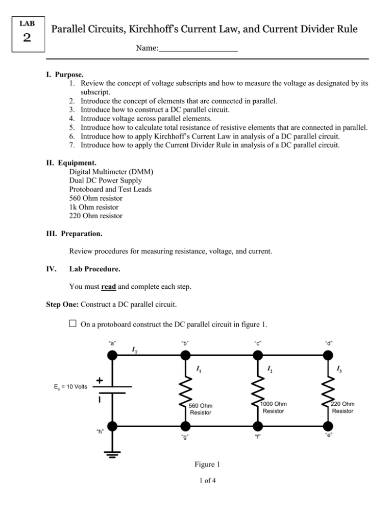
LAB 2 Parallel Circuits, Kirchhoff’s Current Law, and Current Divider Rule Name:________________ I. Purpose. 1. Review the concept of voltage subscripts and how to measure the voltage as designated by its subscript. 2. Introduce the concept of elements that are connected in parallel. 3. Introduce how to construct a DC parallel circuit. 4. Introduce voltage across parallel elements. 5. Introduce how to calculate total resistance of resistive elements that are connected in parallel. 6. Introduce how to apply Kirchhoff’s Current Law in analysis of a DC parallel circuit. 7. Introduce how to apply the Current Divider Rule in analysis of a DC parallel circuit. II. Equipment. Digital Multimeter (DMM) Dual DC Power Supply Protoboard and Test Leads 560 Ohm resistor 1k Ohm resistor 220 Ohm resistor III. Preparation. Review procedures for measuring resistance, voltage, and current. IV. Lab Procedure. You must read and complete each step. Step One: Construct a DC parallel circuit. □ On a protoboard construct the DC parallel circuit in figure 1. “a” T IT “b” “c” “d” T T T I1 I2 I3 Es = 10 Volts 1000 Ohm Resistor 560 Ohm Resistor T “h” 220 Ohm Resistor T T T “g” “f” “e” Figure 1 1 of 4 A Practical Exercise Step Two: Verify voltages of parallel elements and Kirchhoff’s current law. Elements or branches are said to be in parallel connection when they have exactly two nodes in common, and therefore voltages across all parallel elements in a circuit will be the same. Kirchhoff’s current law states that the summation of currents entering a node is equal to the summation of currents leaving that node. □ Measure the voltages and currents indicated in the table below. Remember the current that you wish to measure must pass through the DMM. It may be difficult to visualize how to measure the current through each resistor. Figure 2 depicts how to measure current through the 560 ohm resistor. Use this figure as a guide for your other current measurements. “a” “b” “c” T T T DMM T I1 560 Ohm Resistor T “g” Figure 2 Measured voltage values Measured current values Vah IT Vbg I1 Vcf I2 Vde I3 Are your measured DC voltage values the same? _____________ Why? ______________________________________________________________________________ ____________________________________________________________________________________ 2 of 4 A Practical Exercise □ In figure 3 indicate the direction of the DC currents in all branches and the polarity of the DC voltages across the voltage source and resistors. “a” “b” “c” “d” T T T T T T T T “g” “f” “h” “e” Figure 3 □ Verify Kirchhoff’s Current Law Σ Ientering node = Σ Ileaving node Σ ___________= Σ______________ Do your measured DC current values verify KCL? _________________________________ Step Three: Resistors in parallel. □ Calculate the equivalent resistance, RT, as seen by the source. RT = ________ Is RT smaller or larger than the smallest resistor in the circuit? smaller or larger If the same resistors were connected in series, would they have a greater equivalent resistance than the equivalent resistance of this parallel circuit? ___________________________ □ Measure RT, as seen by the source. RT(measured) = ________ 3 of 4 A Practical Exercise Step Four: Current Divider Rule. The current divider rule can be used to determine how current entering a node is split between the various parallel resistors connected to the node. IX = (RT / RX) IT; IX is the current through RX, RT is the total resistance of parallel resistors, and IT is the total source current entering the parallel circuit. □ Verify your measured branch currents using your measured total source current, IT, your calculated total equivalent resistance, RT, and the given resistor values. Calculated current values I1 I2 I3 From this practical exercise can we conclude that most of the current in a parallel circuit will follow the path of least or most resistance? least or most 4 of 4


