cathode ray oscilloscope (cro)
advertisement

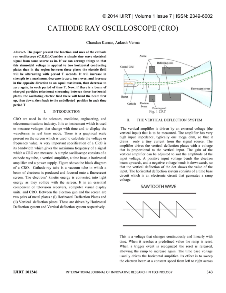
© 2014 IJIRT | Volume 1 Issue 7 | ISSN: 2349-6002 CATHODE RAY OSCILLOSCOPE (CRO) Chandan Kumar, Ankush Verma Abstract- The paper present the function and uses of the cathode ray oscilloscope (C.R.O.).Consider a simple sine wave electrical signal from some source as in. If we can arrange things so that this sinusoidal voltage is applied to two horizontal conducting plates then in the region between these plates the electric field will be alternating with period T seconds. It will increase in strength to a maximum, decrease to zero, turn over, and increase in the opposite direction to an equal maximum, then decrease to zero again, in each period of time T. Now, if there is a beam of charged particles (electrons) streaming between these horizontal plates, the oscillating electric field there will bend the beam first up, then down, then back to the undeflected position in each time period T I. INTRODUCTION CRO are used in the sciences, medicine, engineering, and telecommunications industry. It is an instrument which is used to measure voltages that change with time and to display the waveforms in real time mode. There is a graphical scale present on the screen which is used to calculate the voltage or frequency value. A very important specification of a CRO is its bandwidth which gives the maximum frequency of a signal which a CRO can measure. A simple oscilloscope consists of a cathode ray tube, a vertical amplifier, a time base, a horizontal amplifier and a power supply. Figure shows the block diagram of a CRO. Cathode-ray tube is a vacuum tube in which a beam of electrons is produced and focused onto a fluorescent screen. The electrons’ kinetic energy is converted into light energy as they collide with the screen. It is an essential component of television receivers, computer visual display units, and CRO. Between the electron gun and the screen are two pairs of metal plates : (i) Horizontal Deflection Plates and (ii) Vertical deflection plates. These are driven by Horizontal Deflection system and Vertical deflection system respectively. Fig. 1 CRT II. THE VERTICAL DEFLECTION SYSTEM The vertical amplifier is driven by an external voltage (the vertical input) that is to be measured. The amplifier has very high input impedance, typically one mega ohm, so that it draws only a tiny current from the signal source. The amplifier drives the vertical deflection plates with a voltage that is proportional to the vertical input. The gain of the vertical amplifier can be adjusted to suit the amplitude of the input voltage. A positive input voltage bends the electron beam upwards, and a negative voltage bends it downwards, so that the vertical deflection of the dot shows the value of the input. The horizontal deflection system consists of a time base circuit which is an electronic circuit that generates a ramp voltage. This is a voltage that changes continuously and linearly with time. When it reaches a predefined value the ramp is reset. When a trigger event is recognized the reset is released, allowing the ramp to increase again. The time base voltage usually drives the horizontal amplifier. Its effect is to sweep the electron beam at a constant speed from left to right across IJIRT 101246 INTERNATIONAL JOURNAL OF INNOVATIVE RESEARCH IN TECHNOLOGY 343 © 2014 IJIRT | Volume 1 Issue 7 | ISSN: 2349-6002 the screen, then quickly return the beam to the left in time to begin the next sweep. III. FEATURES AND USES Description: The basic oscilloscope, as shown in the illustration, is typically divided into four sections: the display, vertical controls, horizontal controls and trigger controls. The display is usually a CRT or LCD panel which is laid out with both horizontal and vertical reference lines referred to as the graticule. In addition to the screen, most display sections are equipped with three basic controls: a focus knob, an intensity knob and a beam finder button. The vertical section controls the amplitude of the displayed signal. This section carries a Volts-per-Division (Volts/Div) selector knob, an AC/DC/Ground selector switch and the vertical (primary) input for the instrument. Additionally, this section is typically equipped with the vertical beam position knob. The horizontal section controls the time base or "sweep" of the instrument. The primary control is the Seconds-per-Division (Sec/Div) selector switch. Also included is a horizontal input for plotting dual X-Y axis signals. The horizontal beam position knob is generally located in this section. The trigger section controls the start event of the sweep. The trigger can be set to automatically restart after each sweep or it can be configured to respond to an internal or external event. The principal controls of this section will be the source and coupling selector switches. An external trigger input (EXT Input) and level adjustment will also be included. coaxial connector, then a simple coaxial cable is used; otherwise, a specialized cable called a "scope probe", supplied with the oscilloscope, is used. In general, for routine use, an open wire test lead for connecting to the point being observed is not satisfactory, and a probe is generally necessary. General-purpose oscilloscopes usually present an input impedance of 1 mega ohm in parallel with a small but known capacitance such as 20 picofarads. This allows the use of standard oscilloscope probes. Scopes for use with very high frequencies may have 50-ohm inputs, which must be either connected directly to a 50-ohm signal source or used with Z0 or active probes. Probes Open wire test leads (flying leads) are likely to pick up interference, so they are not suitable for low level signals. Furthermore, the leads have a high inductance, so they are not suitable for high frequencies. Using a shielded cable (i.e., coaxial cable) is better for low level signals. Coaxial cable also has lower inductance, but it has higher capacitance: a typical 50 ohm cable has about 90 pF per meter. Consequently, a one meter direct (1X) coaxial probe will load a circuit with a capacitance of about 110 pF and a resistance of 1 megohm. Probes with 10:1 attenuation are by far the most common; for large signals (and slightly-less capacitive loading), 100:1 probes are not rare. There are also probes that contain switches to select 10:1 or direct (1:1) ratios, but one must be aware that the 1:1 setting has significant capacitance (tens of pF) at the probe tip, because the whole cable's capacitance is now directly connected. CRO controls from the front panel Size and portability Most modern oscilloscopes are lightweight, portable instruments that are compact enough to be easily carried by a single person. In addition to the portable units, the market offers a number of miniature battery-powered instruments for field service applications. Laboratory grade oscilloscopes, especially older units which use vacuum tubes, are generally bench-top devices or may be mounted into dedicated carts. Special-purpose oscilloscopes may be rack-mounted or permanently mounted into a custom instrument housing. Inputs The signal to be measured is fed to one of the input connectors, which is usually a coaxial connector such as a BNC or UHF type. Bindin posts or banana plugs may be used for lower frequencies. If the signal source has its own IJIRT 101246 Front panel of CRO 1. Intensity: This knob controls the brightness of the trace by adjusting the number of electrons emerging from the gun INTERNATIONAL JOURNAL OF INNOVATIVE RESEARCH IN TECHNOLOGY 344 © 2014 IJIRT | Volume 1 Issue 7 | ISSN: 2349-6002 2. Focus: This control is for making the trace on the screen sharper. It is connected to the anode of the electron gun whose voltage collimates the electron beam. undergo deflection according to right angle superposition of two sine waves. It will trace lissajous figures. 3.Vertical Position & Horizontal Position: Through these controls the beam can be positioned at variable vertical or horizontal positions as desired. These knobs apply a dc voltage to the vertical and horizontal deflection plates. 4.V/Div: This control is used to control the voltage sensitivity. This is internally connected to an attenuator of the vertical system. It determines the voltage required by the vertical plates to deflect the beam vertically by one division. 5. Time / Div: This determines the time taken for the spot to move horizontally across one division of the screen when the sweep is generated by triggering process. The signal which is fed to the vertical deflection plates provides the triggering to the waveform. Each position of the time/ div knob is applicable for a particular frequency. This determines the horizontal sensitivity of the observed signal. 6. Trigger Source: This selects the source of the trigger to be applied to the saw tooth waveform. There are usually three possible sources (i) Internal: This is mostly used for all applications. The vertical signal applies the triggering signal. (ii) Line:This is generally used when the voltage to be measured is related to the line voltage. This selects the 50Hz line voltage. (iii) Ext .In this case an external signal is applied to trigger the saw tooth waveform. 7. Slope: This determines whether the time base circuit responds to the positive or negative slope of the triggering waveform. 8. Level: This determines the amplitude level on the triggering waveform which can start the sweep 9. AC, DC, GND: This selects the coupling mechanism for the input signal to the CRO. In dc mode the vertical amplifier receives both ac and dc components of the input signal. In ac mode the coupling capacitor blocks all dc components and displays only pure ac waveform. In gnd configuration, the input signal is grounded and one gets a straight line. To measure the dc component of any signal (ac or dc), one has to switch from ac to dc mode and observe the vertical shift of the waveform. The amount of vertical shift in volts gives the corresponding dc component. 10. X-Y mode: In this mode of operation two signals are superimposed at right angles on each other. The saw tooth time base circuit is disconnected from the horizontal deflection plates and the external signal which s fed to channel two is given to time base instead. Hence if two sine waves are fed to two channels respectively then the electron beam will IJIRT 101246 A sine wave defining amplitude and freq. Types and models 1) 2) 3) 4) 5) 6) 7) Cathode-ray oscilloscope (CRO) Dual-beam oscilloscope Analog storage oscilloscope Digital oscilloscopes Mixed-signal oscilloscopes Handheld oscilloscopes PC-based oscilloscopes IV. CONCLUSION The four parts of the oscilloscope CRT are designed to create and direct an electron beam to a screen to form an image. The oscilloscope links to a circuit that directly connects to the vertical deflection plates while the horizontal plates have linearly increasing charge to form a plot of the circuit voltage over time. In an operating cycle, the heater gives electrons in the cathode enough energy to escape. The electrons are attracted to the accelerating anode and pulled through a control grid that regulates the number of electrons in the beam, a focusing anode that controls the width of the beam, and the accelerating anode itself. The vertical and horizontal deflection plates create electric fields that bend the beam of electrons. The electrons finally hit the fluorescent screen, which absorbs the energy from the electron beam and emits it in the form of light to display an image at the end of the glass tube. V. ACKNOWLEDGMENT We hereby acknowledge and thank the authors & websites listed in the references for the valuable information. REFERENCES 1. Electronic Instrumentation and Measurement Techniques, 3rd Edition, by W.D.Cooper and A.D. Helfrick, PHI INTERNATIONAL JOURNAL OF INNOVATIVE RESEARCH IN TECHNOLOGY 345 © 2014 IJIRT | Volume 1 Issue 7 | ISSN: 2349-6002 2. 3. 4. http://acept.la.asu.edu/courses/phs110/expmts/exp13a .html http://boson.physics.sc.edu/~hoskins/Demos/Cathode Ray.html http://en.wikipedia.org/wiki/Oscilloscope IJIRT 101246 INTERNATIONAL JOURNAL OF INNOVATIVE RESEARCH IN TECHNOLOGY 346


