Document 17961731
advertisement
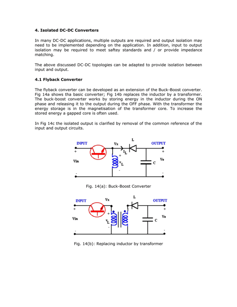
4. Isolated DC-DC Converters In many DC-DC applications, multiple outputs are required and output isolation may need to be implemented depending on the application. In addition, input to output isolation may be required to meet saftey standards and / or provide impedance matching. The above discussed DC-DC topologies can be adapted to provide isolation between input and output. 4.1 Flyback Converter The flyback converter can be developed as an extension of the Buck-Boost converter. Fig 14a shows tha basic converter; Fig 14b replaces the inductor by a transformer. The buck-boost converter works by storing energy in the inductor during the ON phase and releasing it to the output during the OFF phase. With the transformer the energy storage is in the magnetisation of the transformer core. To increase the stored energy a gapped core is often used. In Fig 14c the isolated output is clarified by removal of the common reference of the input and output circuits. Fig. 14(a): Buck-Boost Converter Fig. 14(b): Replacing inductor by transformer Fig. 14(c): Flyback converter re-configured 4.2 Forward Converter The concept behind the foward converter is that of the ideal transformer converting the input AC voltage to an isolated secondary output voltage. For the circuit in Fig. 15, when the transistor is ON, Vin appears across the primary and then generates The diode D1 on the secondary ensures that only positive voltages are applied to the output circuit while D2 provides a circulating path for inductor current if the transformer voltage is zero or negative. Fig. 15: Forward Converter The problem with the operation of the circuit in Fig 15 is that only positive voltage is applied across the core, thus flux can only increase with the application of the supply. The flux will increase until the core saturates when the magnetising current increases significantly and circuit failure occurs. The transformer can only sustain operation when there is no significant DC component to the input voltage. While the switch is ON there is positive voltage across the core and the flux increases. When the switch turns OFF we need to supply negative voltage to rset the core flux. The circuit in Fig. 16 shows a tertiary winding with a diode connection to permit reverse current. Note that the "dot" convention for the tertiary winding is opposite those of the other windings. When the switch turns OFF current was flowing in a "dot" terminal. The core inductance act to continue current in a dotted terminal, thus Fig. 16: Forward converter with tertiary winding For further reading: [1] "Power Electronics: Converters, Applications and Design", Mohan, Undeland and Robbins, Wiley, 1989. Copyright © G. Ledwich 1998.
