Jarvis - Voice Controlled Devices
advertisement
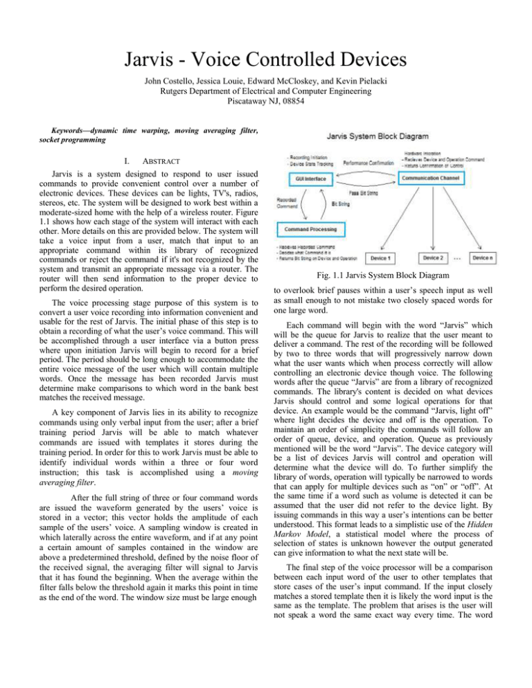
Jarvis - Voice Controlled Devices John Costello, Jessica Louie, Edward McCloskey, and Kevin Pielacki Rutgers Department of Electrical and Computer Engineering Piscataway NJ, 08854 Keywords—dynamic time warping, moving averaging filter, socket programming I. ABSTRACT Jarvis is a system designed to respond to user issued commands to provide convenient control over a number of electronic devices. These devices can be lights, TV's, radios, stereos, etc. The system will be designed to work best within a moderate-sized home with the help of a wireless router. Figure 1.1 shows how each stage of the system will interact with each other. More details on this are provided below. The system will take a voice input from a user, match that input to an appropriate command within its library of recognized commands or reject the command if it's not recognized by the system and transmit an appropriate message via a router. The router will then send information to the proper device to perform the desired operation. The voice processing stage purpose of this system is to convert a user voice recording into information convenient and usable for the rest of Jarvis. The initial phase of this step is to obtain a recording of what the user’s voice command. This will be accomplished through a user interface via a button press where upon initiation Jarvis will begin to record for a brief period. The period should be long enough to accommodate the entire voice message of the user which will contain multiple words. Once the message has been recorded Jarvis must determine make comparisons to which word in the bank best matches the received message. A key component of Jarvis lies in its ability to recognize commands using only verbal input from the user; after a brief training period Jarvis will be able to match whatever commands are issued with templates it stores during the training period. In order for this to work Jarvis must be able to identify individual words within a three or four word instruction; this task is accomplished using a moving averaging filter. After the full string of three or four command words are issued the waveform generated by the users’ voice is stored in a vector; this vector holds the amplitude of each sample of the users’ voice. A sampling window is created in which laterally across the entire waveform, and if at any point a certain amount of samples contained in the window are above a predetermined threshold, defined by the noise floor of the received signal, the averaging filter will signal to Jarvis that it has found the beginning. When the average within the filter falls below the threshold again it marks this point in time as the end of the word. The window size must be large enough Fig. 1.1 Jarvis System Block Diagram to overlook brief pauses within a user’s speech input as well as small enough to not mistake two closely spaced words for one large word. Each command will begin with the word “Jarvis” which will be the queue for Jarvis to realize that the user meant to deliver a command. The rest of the recording will be followed by two to three words that will progressively narrow down what the user wants which when process correctly will allow controlling an electronic device though voice. The following words after the queue “Jarvis” are from a library of recognized commands. The library's content is decided on what devices Jarvis should control and some logical operations for that device. An example would be the command “Jarvis, light off” where light decides the device and off is the operation. To maintain an order of simplicity the commands will follow an order of queue, device, and operation. Queue as previously mentioned will be the word “Jarvis”. The device category will be a list of devices Jarvis will control and operation will determine what the device will do. To further simplify the library of words, operation will typically be narrowed to words that can apply for multiple devices such as “on” or “off”. At the same time if a word such as volume is detected it can be assumed that the user did not refer to the device light. By issuing commands in this way a user’s intentions can be better understood. This format leads to a simplistic use of the Hidden Markov Model, a statistical model where the process of selection of states is unknown however the output generated can give information to what the next state will be. The final step of the voice processor will be a comparison between each input word of the user to other templates that store cases of the user’s input command. If the input closely matches a stored template then it is likely the word input is the same as the template. The problem that arises is the user will not speak a word the same exact way every time. The word will likely be spoken at a different pitch or speed then what the template contains. To take these variations into account matching is done through a dynamic time warping function. The dynamic time warping function allows comparison between two signals that vary in time or speed. This function warps the input signal non-linearly to compare each signal at different points in time with respect to each other. From there a path finding algorithm can be used to calculate a distance of how well these signals represent one another. The lower the calculated distance the better each signal represents one another. This function will be applied to each word spoken as well as each template that the word has been categorized to and return the minimum value to decide which word was likely to be spoken. This finally generates a bit sequence output that is passed onto the communication channel stage. The Jarvis communication channel will be how the processor will speak to the connected devices. Socket programming was used in Matlab to have the processor talk to each device. Socket programming has two parts a server and client. The client listens to a specific port on the server’s IP address. The server opens the port the client is listening to and sends data into it. The client will then take in the data the servers sends along the port. The processor in Jarvis is the server for the socket programming. The devices will be GUI’s which represent different devices and are the client for the socket programming. Each device will be listening to different ports and the processor will decide which device the command was for and will send it to the appropriate port. The GUI’s will then processes the message and perform the function within the message. For example if the user tells the TV channel to go up the GUI will display the channel going up. The devices, just like in real life, can have buttons change the status of its functions. The message is a 40 byte message. The first five bytes represent the devices meaning there is a max of 32 devices connected at once. Each device has a unique name. The next 30 bytes represent all the possible commands a device can receive. This means the total amount of unique commands can be 230. The last five bytes represent the action for the device to take. So if the user inputs “TV Volume Up.” The first five bytes will represent the TV, the next 30 will represent Volume, and the last five will represent up. The socket programming did all of this correctly sending the command without error and properly changed the device’s status. Future work that could be done with the socket programming is to have the devices constantly listen for messages from the port while also having the ability to have the devices changed using buttons. Matlab presented this limitation in the program since it cannot perform two operations at the same time. Another future work that can be done is to have the devices communicate back to the processor to let the processor know when something has been changed on the device by the user pressing a button.
