SECTION LOW-VOLTAGE DISTRIBUTION TRANSFORMERS TP-1S
advertisement
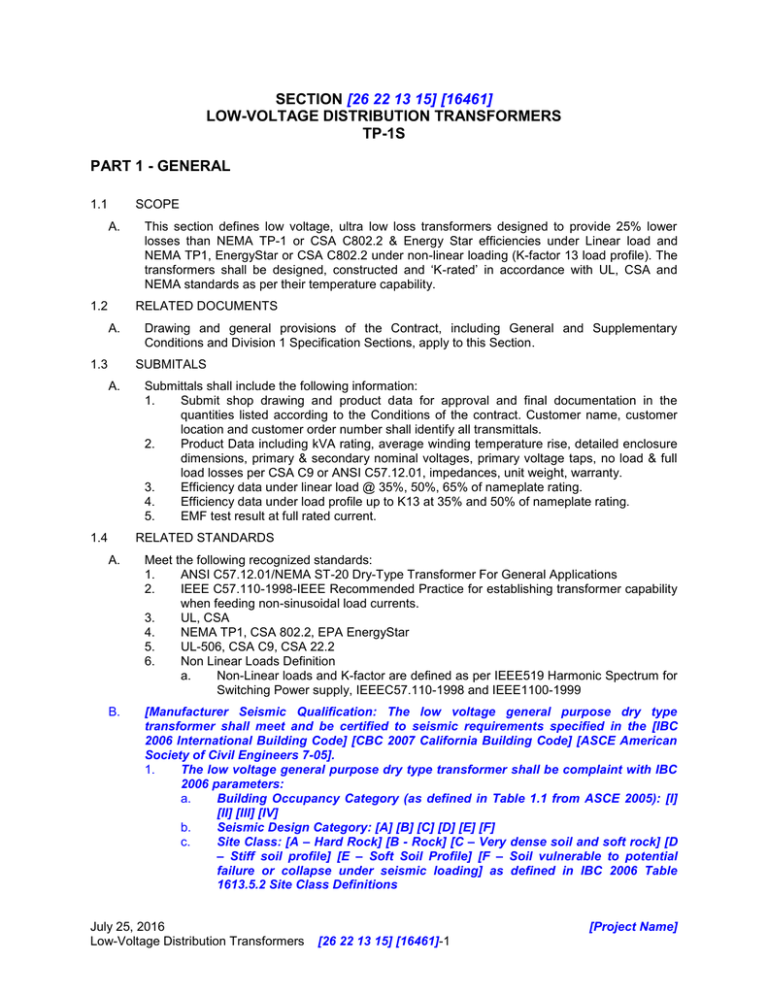
SECTION [26 22 13 15] [16461] LOW-VOLTAGE DISTRIBUTION TRANSFORMERS TP-1S PART 1 - GENERAL 1.1 SCOPE A. 1.2 This section defines low voltage, ultra low loss transformers designed to provide 25% lower losses than NEMA TP-1 or CSA C802.2 & Energy Star efficiencies under Linear load and NEMA TP1, EnergyStar or CSA C802.2 under non-linear loading (K-factor 13 load profile). The transformers shall be designed, constructed and ‘K-rated’ in accordance with UL, CSA and NEMA standards as per their temperature capability. RELATED DOCUMENTS A. 1.3 Drawing and general provisions of the Contract, including General and Supplementary Conditions and Division 1 Specification Sections, apply to this Section. SUBMITALS A. 1.4 Submittals shall include the following information: 1. Submit shop drawing and product data for approval and final documentation in the quantities listed according to the Conditions of the contract. Customer name, customer location and customer order number shall identify all transmittals. 2. Product Data including kVA rating, average winding temperature rise, detailed enclosure dimensions, primary & secondary nominal voltages, primary voltage taps, no load & full load losses per CSA C9 or ANSI C57.12.01, impedances, unit weight, warranty. 3. Efficiency data under linear load @ 35%, 50%, 65% of nameplate rating. 4. Efficiency data under load profile up to K13 at 35% and 50% of nameplate rating. 5. EMF test result at full rated current. RELATED STANDARDS A. Meet the following recognized standards: 1. ANSI C57.12.01/NEMA ST-20 Dry-Type Transformer For General Applications 2. IEEE C57.110-1998-IEEE Recommended Practice for establishing transformer capability when feeding non-sinusoidal load currents. 3. UL, CSA 4. NEMA TP1, CSA 802.2, EPA EnergyStar 5. UL-506, CSA C9, CSA 22.2 6. Non Linear Loads Definition a. Non-Linear loads and K-factor are defined as per IEEE519 Harmonic Spectrum for Switching Power supply, IEEEC57.110-1998 and IEEE1100-1999 B. [Manufacturer Seismic Qualification: The low voltage general purpose dry type transformer shall meet and be certified to seismic requirements specified in the [IBC 2006 International Building Code] [CBC 2007 California Building Code] [ASCE American Society of Civil Engineers 7-05]. 1. The low voltage general purpose dry type transformer shall be complaint with IBC 2006 parameters: a. Building Occupancy Category (as defined in Table 1.1 from ASCE 2005): [I] [II] [III] [IV] b. Seismic Design Category: [A] [B] [C] [D] [E] [F] c. Site Class: [A – Hard Rock] [B - Rock] [C – Very dense soil and soft rock] [D – Stiff soil profile] [E – Soft Soil Profile] [F – Soil vulnerable to potential failure or collapse under seismic loading] as defined in IBC 2006 Table 1613.5.2 Site Class Definitions July 25, 2016 Low-Voltage Distribution Transformers [Project Name] [26 22 13 15] [16461]-1 Ip – Importance Factor: [1.5 – Components must function after an earthquake for life safety purposes (Building Occupancy Code IV)] [1.25 - Buildings and structures that represent a substantial hazard to human life in the event of failure or that can cause substantial economic impact or mass disruption of day-to-day civilian life (Building Occupancy Code III)] [1.0 – Non-essential buildings. Function not life critical. (Building Occupancy Code I and II)] e. Ss – Mapped Spectral Accelerations for Short Periods at 0.2 seconds – [0.89g] [1.8g] f. Sds – 5% Damped Design Spectral Response Accelerations for Short Periods at 0.2 seconds – [0.6] [1.2] Note: This value is typically 2/3 of Ss. g. z/h – Height factor ratio: [___] Note: Ratio is a calculated value equal to the floor the gear is installed on divided by 12. A 6th floor installation is a 0.5 value. A basement or ground floor installation is a 0.0 value. Equipment shall be designed to be located in a concrete and steel, momentresisting frame building not exceeding 12 stories in height with a minimum story height of 10 feet.] d. 2. 1.5 QUALITY ASSURANCE A. 1.6 Manufacturers Qualifications: The manufacturer of this equipment shall have a minimum of 5 years experience producing similar electrical products. 1. Production tests. Test each unit according to: a. NEMA ST20 b. CSA C9 c. NEMA TP2 2. Perform a Type Test for each model design and submit report. 3. Type test to include: a. Positive sequence impedance b. Heat run test for K-factor rating compliance per UL & CSA c. Demonstrated temperature rise with non-linear load (with K13 load profile). d. Percentage regulation at 100% and provide regulation at 80% power factor e. No load and full load losses in watts f. Efficiency under linear load at 15%, 25%, 35%, 50%, 65%, 75% and 100% and under non-linear with a load profile up to K13 at 35% and 50%. Non-linear load test bench results must be used as the source of test data. g. Sound level in decibels DELIVERY, STORAGE AND HANDLING A. Store and handle in strict compliance with manufacturer’s instructions and recommendations. Protect from potential damage from weather and construction operations. Store so condensation will not form on or in the transformer housing and if necessary, apply temporary heat where required to obtain suitable service conditions. B. Handle transformer using proper equipment for lifting and handling, use when necessary lifting eye and/or brackets provided for that purpose. PART 2 - PRODUCTS 2.1 2.2 MANUFACTURERS A. [The transformer shall be Siemens Sentron TP1S Super Energy Efficient K-Factor transformer or pre-approved equal. Approved manufacturers are as follows: 1. SIEMENS Industry - Sentron 2. .] B. Substitutions shall be permitted, subject to meeting all requirements of this specification. GENERAL CONSTRUCTION July 25, 2016 Low-Voltage Distribution Transformers [Project Name] [26 22 13 15] [16461]-2 A. Three-phase transformers 15kVA and larger, shall be ventilated type. All three-phase transformers shall be constructed with three windings and a single core. [Match to the Taps you pick in Section 2.3.H. Delete this next sentence if you pick no taps - The primary side taps of each transformer shall be provided with taps that meet or exceed NEMA standards.] B. Wiring terminations: Bring out primary and secondary terminations to terminals on the same side of the transformer mounted on insulated support. Provide mechanical lugs on primary, secondary and neutral (double) for customer terminations. C. Provide ground bar kit and neutral to ground bond jumper terminated at ground bar. Provide mechanical lugs mounted on the ground bar for input ground bond, output ground bond and external ground. D. If shipping to Europe, transformer will also have to be manufactured in accordance to CE standards and carry a CE mark. 2.3 GENERAL REQUIREMENTS A. Voltage And KVA Requirements 1. Primary Voltage: [208 V] [480 V] [600 V] [As shown on drawings] 2. Secondary Voltage: [208/120 V] [480/277 V] [600/347 V] [As shown on drawings] 3. kVA Rating: [15 kVA] [30 kVA] [45 kVA] [75 kVA] [112.5 kVA] [150 kVA] [225 kVA] [300 kVA] [500 kVA] [750 kVA] [As shown on drawings] 4. System Frequency: [60 Hz] [50 Hz] [As shown on drawings] 5. Typical impedance at 60Hz: 1.8% to 4.5% 15kVA to 75kVA, 2.2% to 6.5% over 75kVA. 6. Nameplate Rating (rated for non-linear loads, 60Hz): K13 B. Efficiencies 1. Exceeds NEMA TP1, EPA ENERGY STAR Energy Savings Program and CSA C802.2 efficiencies at an operating range from 35% to 65% of rated load. 2. Efficiency performance will be 25% better than TP1 and C802.2 standards when measured under a linear load profile. 3. Efficiencies will meet or exceed TP1 and C802.2 standards at an operating range from 35% to 50% of rated load when measured under a non-linear load profile up to K20. 4. Efficiencies, no-load losses, load losses and impedance values will be calculated at temperature reference of 75°C at UPF. C. Noise Levels 1. Noise levels shall be 3 dB lower than NEMA ST-20 2. EMF level, not to be higher than 10mG top, 10mG side and 10mG at one meter 3. Electrostatic shield for common and transverse noise attenuation a. 80 dB Common Mode b. 20 dB Transverse Mode D. Type: 1. ANN, convection air cooled E. Insulation Class: 1. [220°C system] 2. [200°C system] 3. [As shown on drawings] F. Temperature Rise (under linear loading): 1. [150°C] 2. [130°C] 3. [115°C] 4. [80°C] 5. [As shown on drawings] G. Secondary Neutral Conductor: July 25, 2016 Low-Voltage Distribution Transformers [Project Name] [26 22 13 15] [16461]-3 H. 1. Rating shall be 200% of the secondary phase conductor ampacity. Taps: 1. 2. 3. 4. 5. 6. [1 x ± 5% (1FCAN, 1FCBN)] [2 x ± 2.5% (2FCAN, 2FCBN)] [2 x +2.5%, 4 x -2.5% (2FCAN, 4FCBN)] [2 x - 5% (2FCBN)] [None] [As shown on drawings] I. Core Construction: 1. High grade non-aging, fully processed silicon steel laminations or better. J. Coil Conductors: 1. Continuous [aluminum] [copper] windings, with terminations brazed or welded up to 75kVA and bolted 112.5 kVA and up. K. Impregnation: 1. Vacuum impregnated polyester resin. L. Inrush Current: 1. 10 times full load rating (max.) M. Excitation Current: 1. 5% of full load current rating (max.) N. Enclosure: 1. Ventilated NEMA 3R enclosure designed to prevent hand or rod contact with live parts [totally enclosed] [As shown on drawings]. 2. Finish: a. [ANSI 61 Grey suitable for UL50 outdoor applications] b. [As shown on drawings] O. Anti-Vibration Pads: 1. Shall be used between the core and the enclosure P. Core & Coil Assembly 1. Shall be grounded to the enclosure with a flexible copper grounding strap or equivalent. Q. Mounting: 1. Ventilated units up to 750 lbs.: a. Suitable for wall, floor or ceiling mounting with required drip plate. 2. Ventilated units over 750 lbs.: a. Suitable for floor mounting only. 2.4 [OPTIONS A. The transformer shall include the following optional items: 1. [Over-Temperature switches wired to internal terminal strip. Temperatures specified for use with class 220°C insulation systems. Standard configuration is N.C. opening on high temperature. Optional configuration is N.O. closing on high temperature. Installation options: [one switch: 170°C or 200°C on center coil] [two switches: 170°C and 200°C on center coil] [six switches: one 170°C and one 200°C on each of the 3 coils]] 2. [SPD - Surge Protection Device] 3. [EMF level, not to be higher than 10mG top, 10mG side and 10mG at one meter.]] PART 3 - EXECUTION 3.1 INSTALLATION A. Install per manufacturer’s recommendations and contract documents. July 25, 2016 Low-Voltage Distribution Transformers [Project Name] [26 22 13 15] [16461]-4 1. 2. 3. 4. 5. 6. 7. 8. 9. 10. 3.2 The installing contractor shall install the Siemens TP1S Super Energy Efficient K-Factor transformer per the manufacturers recommended installation practices as found in the installation, operation, and maintenance manual and comply with all applicable codes. Make sure that the transformer is level. Check for damage and loose connections. Mount transformer to comply with all applicable codes. Install seismic restraint where indicated on the drawing. Coordinate all work in this section with all work of other sections. Perform insulation resistance testing on all windings; HV to LV, HV to Grd, LV to Grd. Perform turns ratio testing to ensure transformer is fully functional. Prior to energizing transformer for service, verify primary incoming voltage and if necessary adjust primary taps to match system voltage. Provide a certified test report for all testing done in items G, H, and I. ADJUSTING AND CLEANING A. On completion of installation, inspect components. Remove paint splatters and other spots, dirt and debris. Repair scratches and mars on finish to match original finish. Clean components internally using methods and materials recommended by manufacturer. B. Adjust transformer taps to provide optimum voltage conditions at utilization equipment throughout normal operating cycle of facility. Record primary and secondary voltages and tap settings and submit with test results. 3.3 TESTING A. Include the following minimum inspections and tests according to manufacturer's written instructions. Comply with IEEE C57.12.91 for test methods and data correction factors. B. Inspect accessible components for cleanliness, mechanical and electrical integrity and damage or deterioration. Verify that temporary shipping bracing has been removed. Include internal inspection through access panels and covers. C. Inspect bolted electrical connections for tightness according to manufacturer's published torque values or, if not available, those specified in UL 486A and UL 486B. 3.4 WARRANTY A. The transformer shall carry a 10 year limited warranty. B. Detailed warranty information shall be available in the manufacturer’s published warranty. 3.5 START-UP SERVICES A. [Add text here, if desired] END OF SECTION July 25, 2016 Low-Voltage Distribution Transformers [Project Name] [26 22 13 15] [16461]-5
