Document 16060180
advertisement

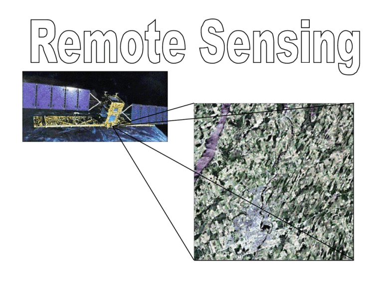
Remote Sensing Definition: “Remote sensing is the science of acquiring information about the Earth’s surface without actually being in contact with it, by sensing and recording reflected or emitted energy and processing, analyzing and applying that information” Simplest Form of Remote Sensing: Aerial Photography Cartographers take detailed measurements from aerial photos in the preparation of maps Geographers interpret aerial photos to determine land-use, and environmental conditions Aerial photographs are not maps Maps: Directionally and geometrically accurate Aerial photograps: Radial distortion GIS’s can account for radial distortion The Electromagnetic Spectrum Electromagnetic radiation is energy propagated through space between electric and magnetic fields. The electromagnetic spectrum is the extent of that energy from cosmic rays, gamma-rays, X-rays, ultraviolet, visible, infrared and microwave energy Electromagnetic waves can be classified by: FREQUENCY or WAVELENGTH Velocity = Speed of light Electromagnetic Radiation Consists of electrical field (E) and magnetic field (M) Travels at speed of light (C) The shorter the wavelength, the higher the frequency This is important for understanding information obtained in remote sensing Microwaves are longest wavelengths used in remote sensing We are blind to everything except this narrow band UV are shortest wavelengths practical for remote sensing Remote Sensing requires the following: 1. Electromagnetic Energy Source 2. Interaction with a Target 3. Sensor to Record Energy 4. Transmission, Reception and Processing 5. Interpretation 6. Application Electromagnetic Energy Source Illuminates or provides electromagnetic radiation to the target of interest A- Source of Electromagnetic Radiation B- Radiation comes into Contact with Atmosphere C- Radiation Interacts with Target D- Sensor Collects and Records Electromagnetic Radiation E- Recorded Energy Transmitted G to Processing Station (for copy) F- Processed Image Interpreted to Extract Target Info Application Radiation Interacts with Atmosphere Radiation interacts with the atmosphere on the way to the target and as the energy travels from the target to the sensor Interaction with a Target Radiation interacts with target. The nature of this interaction is dependent on the wavelength of the radiation and the nature of the target Sensor A sensor (mounted on satellite/plane/helicopter) collects/records the electromagnetic radiation scattered or emitted by the target Transmission and Processing Recorded energy is transmitted to a processing station to produce an image saved in digital format (or hardcopy) Interpretation Visual interpretation or digital (GIS) interpretation to extract further information about the target Application Information applied to solve a problem * Remote sensing is especially important for extracting information from harsh environments or difficult terrain Transmission through the Atmosphere Some wavelengths of E-M energy are absorbed and scattered more efficiently than others H2O, CO2, and ozone have the strongest absorption spectra Transmission Light moves through a surface Wavelength dependent (eg. leaves) Radiation emitted from Earth is of a much longer wavelength and is of much lesser energy Atmospheric Windows In the diagram below, peaks are windows, while troughs identify wavelengths that are heavily absorbed WINDOWS ABSORPTION Scattering Passive Sensors Measure naturally-available energy (eg. thermal infrared radiation emitted from the Earth 24 hours per day, but solar reflected radiation only during solar day) Active Sensors Sensor emits radiation toward target Reflected radiation in emitted bands are detected and measured (eg. microwaves emitted) When electromagnetic energy strikes molecules or other tiny objects, one of three things happens: 1. 2. 3. REFLECTION ABSORPTION TRANSMISSION Remote sensing is most concerned with REFLECTION of radiation (or emission from the Earth). Reflectance The ratio of the amount of electromagnetic radiation reflected from a surface to the amount originally striking a surface • Specular Reflection Surface is smooth relative to incident wavelength, resulting in mirror-like reflection (reflected in single direction) May help or hinder remote sensing depending on where the sensor is situated • Diffuse Reflection Surface is rough relative to incident wavelength Energy is scattered more or less evenly in all directions Many natural surfaces exhibit a great deal of diffuse reflection Surface types yield distinct spectral responses Examples Water: Longer visible wavelengths absorbed more than shorter visible wavelengths (blue-green) Leaves: Chlorophyll strongly absorbs in blue and red, but reflects green (green colour results) Healthy leaves efficiently reflect near IR Absorption vs. Reflection differ for different wavelengths of electromagnetic radiation Leaves Water Spectral signatures Degree to which an object reflects incident electromagnetic energy in different regions of the electromagnetic spectrum Characteristic signatures can be obtained for specific land surface classes Multispectral sensors detect reflectance in more than one band Characteristic spectral responses of different surface types. Bands are those of the SPOT remote sensing satellite. Visual Interpretation in Remote Sensing and Aerial Photo Interpretation The following visual elements are considered in identifying objects: Tone (Hue or Colour) Brightness or colour of elements on an image. Nothing could be discerned without changes in brightness or colour. Shape Form, structure or general outline of the objects. Regular shapes usually indicate human presence and land-use. Size Absolute size and size relative to background objects (in context of scale of the image) Texture Smoothness or roughness Arrangement and frequency of tonal variation (eg. A forest is rough while an asphalt or cement surface is smooth) Pattern Spatial arrangement of objects gives a clue to object character (eg. random pattern in forest area vs. Shadow May help determine relative height but may also hinder interpretation obscuring objects within Association and Site Relationship between target and other objects: context of an object may lead to its identification Understanding of stratigraphy alters geomorphological interpretation of landscape features Images and Photographs Representation in digital format by subdividing image into equallyshaped areas called pixels The ‘brightness’ of each area can be attributed a numeric value or digital number Information from narrow wavelength ranges can be stored in channels, also called bands Often, data from multiple channels can be represented as one of three primary colours which combine according to brightness. We are, thus, no longer blind to these ’s. Orbits and Swaths Geostationary orbits: Very high altitude satellites (approximately 36 000 km) Focus on the same area of the Earth at all times Continual data collection over a specific area Eg. Weather and communications satellites Near-polar orbits Satellite travels northward on one side of the Earth and then southwards during the second half of its orbit In sun-synchronous orbits, ascending path can be on a shadowed side with the descending path on the sunlit side. Passive sensors would only record data during the descent. Swath The area imaged on the surface. Swaths vary from very small areas (helicopters and planes) to hundreds of kilometres (spaceborne satellites) Earth rotates: Satellite swath may cover new area with each pass Complete coverage of Earth after one cycle of orbits Areas at high latitude generally covered more frequently Spatial Resolution Size of the smallest possible feature that can be detected Instantaneous Field of View (IFOV) is the angular cone of visibility of the sensor (See A at right) This, along with altitude (C), determines the area visible on the ground (B) Examples of Remote Sensing Satellites Each has multiple channels for specific purposes 1. Weather GOES (Geostationary Operational Environmental Satellite) NOAA AVHRR (Advanced Very High Resolution Radiometer) 2. Land Surface Observation Landsat (NOAA) SPOT (Système Pour l’Observation de la Terre) IRS (Indian Remote Sensing) MEIS-II and CASI (Airborne Sensors) 3. Marine Observation CZCS (Coastal Zone Colour Scanner) MOS (Marine Observation Satellite) SeaWiFS (Sea-viewing Wide Field of View Sensor) Applications of Remote Sensing There are many applications of remote sensing, most of which are related to Geography as a discipline Agriculture: Forestry: Hydrology: Land Use: Oceans: Mapping: Crop type, condition and yield, soil characteristics Type, health, biomass, burning, species, deforestation Sea ice, navigation, oil spills, sea surface temperature Resource management, habitat protection, urban sprawl, damage assessment, legal boundaries Currents, winds, waves, phytoplankton concentration, temperature monitoring, navigation routing, traffic density, bathymetry, land-water interface delineation, coastal vegetation Digital Elevation Models (DEM’s), thematic mapping AVHRR Visible, NIR, Thermal 1.1 km Resolution - local area coverage (LAC) 4 km Resolution - global area coverage (GAC) Used for meteorological studies Vegetation pattern analysis Global modeling Broad spectral bands LANDSAT Thematic Mapper Sun-synchronous, near-polar orbit, imaging the same 185 km x 0.474 km ground swath every 16 days Global coverage between 81 degrees north latitude and 81 degrees south latitude Particularly useful in determining land use classes Blue/Green, Green, Red, NIR, MIR, Thermal 30 meter resolution 256 brightness values 7 spectral bands Normalized Difference Vegetative Index (NDVI) NDVI = (NIR - red) / (NIR + red) RADAR - Radio Detection and Ranging Passive Microwave Sensors: Applications include meteorology (atmosphere profiles, water and ozone content), hydrology (soil moisture) and oceanography (sea ice, currents, oil slicks) Active Microwave Sensors: RADAR - Sensor transmits a microwave (or radio) signal toward a target and detects the backscattered portion of the signal Strength of backscattered signal discriminates between targets Time delay between transmitted and reflected signals determines the distance to the target Non-Imaging (eg. altimeters) or Imaging Sensors Imaging Microwave Sensors include RADARSAT (Canada, 1995) RADARSAT, developed by the Canadian Space Agency, is the world’s first, operationally-oriented radar satellite system capable of rapid delivery of large quantities of data Image Processing 1. Preprocessing Radiometric and geometric corrections 2. Image Enhancement Improving contrast, and spatial filtering to enhance specific spatial patterns of interest 3. Image Transformations Combined processing of multiple spectral bands for image enhancement 4. Image Classification and Analysis Digital identification and classification of pixels. Classification: Assigns each pixel to a particular class or theme based on desired statistical characteristics (supervised or unsupervised) Before GIS: Popularity of stack maps Limitation: Restricted to consistent scale, projection and coverage area Advantage of Digital Overlay: 1. Faster 2. Scale, projection and coverage area less problematic (Most applications consist of sources collected by different methods and at different scales) 3. Time and error associated with manual integration and redrafting eliminated Raster or Vector Implementation Raster Implementation of Overlay Overview of Overlay Analysis 1. Three maps represented with a common grid 2. Binary maps converted with Boolean operators such as AND and OR Eg. Suitability Analysis AND = more than one condition must occur simultaneously OR = identifies areas with either condition met Boolean logic: truth tables Exclusionary approaches rely on boolean logic, where the value of the statement, "A is true AND B is true" is determined in a truth table indicated the individual permutations of A and B: AND B is true B is false A is true T F A is false F F The value of the statement, "A is true OR B is true" under the same circumstances: OR B is true B is false A is true T T A is false T F Boolean Logic in Raster Overlay It is often useful to RECLASS your data before performing OVERLAY RECLASS OVERLAY Task: Given vegetation map and elevation map, isolate a vegetation type within a particular altitude range Map 1: Vegetation Map (VEGMAP) Map 2: Digital Elevation Model (DEM1) This requires the use of the AND operation STEP 1: Our vegetation of interest is class 6. Reclass to assign a value of 1 for all values from 6 to just less than 7. All other values are assigned a value of zero. CLASS6 STEP 2: Use the Digital Elevation Model to isolate the elevations between 1700 and 1800 m.a.s.l. In the same way, assign a value of 1 to all values from 1700 to just less than 1801 by using a reclass function. DEM1718 Where do the two isolated characteristics coincide ? Use OVERLAY Multiply file CLASS6 by DEM1718 to produce the output map RESULT. Only pixels with a value of 1 survive to be represented in the output file. RESULT OVERLAY is often used in combination with other operations such as near-neighbour operations Eg. Produce a map of riparian vegetation cover within 100 metres of rivers and streams Locate buffer zone 100m from rivers Overlay with vegetation map Produce resultant map of riparian cover Vector Implementation of Overlay Produces many new polygons due to overlapping Each new polygon has a unique, new identifier The identifier is linked to an attribute table Result is a single layer coverage linked to all attributes


