2. Machining process: 2.1 Dielectric:
advertisement

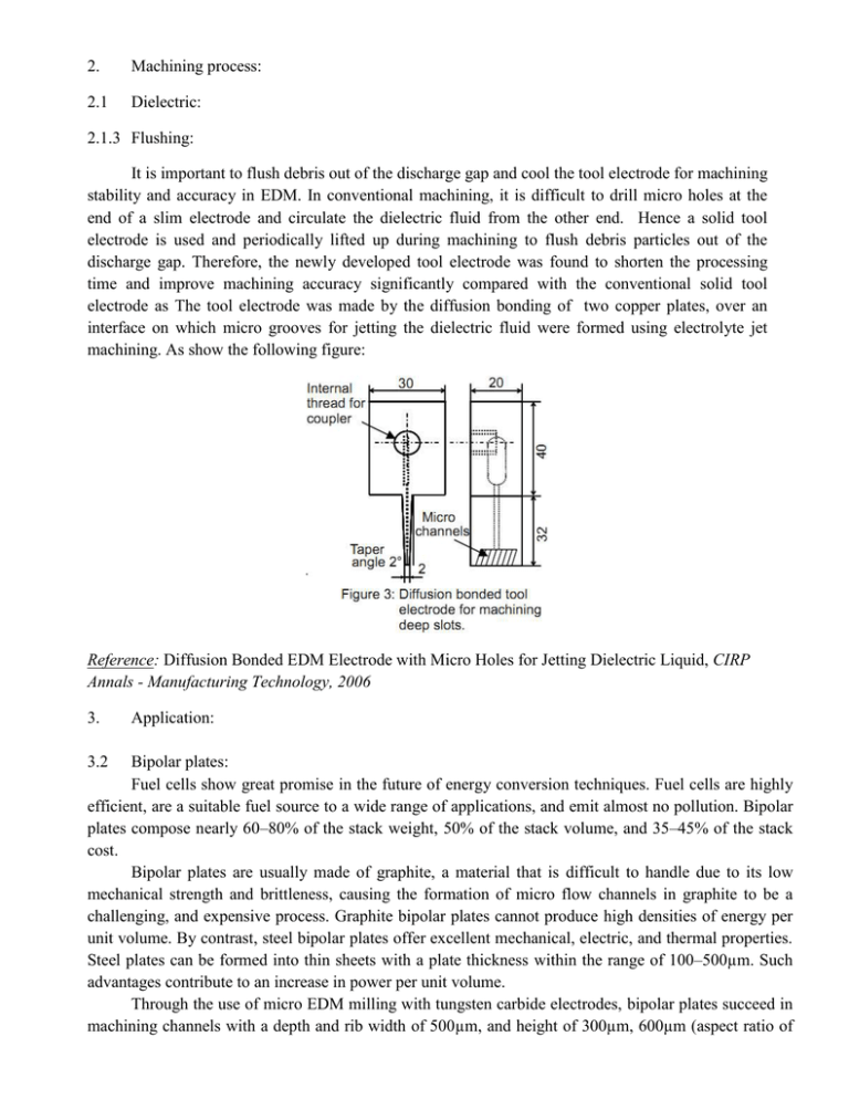
2. Machining process: 2.1 Dielectric: 2.1.3 Flushing: It is important to flush debris out of the discharge gap and cool the tool electrode for machining stability and accuracy in EDM. In conventional machining, it is difficult to drill micro holes at the end of a slim electrode and circulate the dielectric fluid from the other end. Hence a solid tool electrode is used and periodically lifted up during machining to flush debris particles out of the discharge gap. Therefore, the newly developed tool electrode was found to shorten the processing time and improve machining accuracy significantly compared with the conventional solid tool electrode as The tool electrode was made by the diffusion bonding of two copper plates, over an interface on which micro grooves for jetting the dielectric fluid were formed using electrolyte jet machining. As show the following figure: Reference: Diffusion Bonded EDM Electrode with Micro Holes for Jetting Dielectric Liquid, CIRP Annals - Manufacturing Technology, 2006 3. 3.2 Application: Bipolar plates: Fuel cells show great promise in the future of energy conversion techniques. Fuel cells are highly efficient, are a suitable fuel source to a wide range of applications, and emit almost no pollution. Bipolar plates compose nearly 60–80% of the stack weight, 50% of the stack volume, and 35–45% of the stack cost. Bipolar plates are usually made of graphite, a material that is difficult to handle due to its low mechanical strength and brittleness, causing the formation of micro flow channels in graphite to be a challenging, and expensive process. Graphite bipolar plates cannot produce high densities of energy per unit volume. By contrast, steel bipolar plates offer excellent mechanical, electric, and thermal properties. Steel plates can be formed into thin sheets with a plate thickness within the range of 100–500µm. Such advantages contribute to an increase in power per unit volume. Through the use of micro EDM milling with tungsten carbide electrodes, bipolar plates succeed in machining channels with a depth and rib width of 500µm, and height of 300µm, 600µm (aspect ratio of 0.6 and 1.2), respectively, in a reaction area 20mm×20mm, on 50mm×50mm×1mm SUS 316L stainless steel. As the shown figure: Reference: Studies on the fabrication of metallic bipolar plates-Using micro electrical discharge machining milling, Journal of Power Sources, 2010. 3.3 Dry EDM drilling: In conventional EDM, in addition to the problems associated with a complex dielectric supply system, a kerosene or oil-based dielectric causes carbon deposition over the machined surfaces. On the other hand, use of water-based dielectric leads to formation of cracks, electrolysis and corrosion of the EDMed surface. The force generated after the dielectric breakdown in EDM due to expansion and contraction of a bubble formed by evaporation, dissociation and ionization of dielectric liquid and electrode materials is higher in liquid as compared to gas, since expansion of the bubble is prevented by greater inertia and viscosity of the dielectric liquid. Since the electrical permittivity of the liquid medium is higher than the gas medium, the electrostatic force is higher as well. It is known that the liquid dielectric has difficulties in accessing the sparking region, besides its fumes are hazardous to the environment. Therefore dry electrical discharge machining which uses gas as dielectric fluid is proposed. Dry EDM technology overcomes some of these demerits and has a few additional advantages such as formation of thinner white layer, low dielectric constant resulting in easy breaking of dielectric and formation of plasma, lesser viscosity of gas and lower heat concentration causing better debris removal and flushing. In addition, at low discharge energies, single-discharge in dry EDM could give larger MRR and crater radius as compared to that of the conventional liquid dielectric EDM. The dry EDM process is illustrate by the flowing figure: Reference: Experimental characterization of material removal in dry electrical discharge drilling, International Journal of Machine Tools & Manufacture,2010. 3.4 Orbital electrode actuation: Machining technique for micro-EDM that actuates the EDM electrode on an orbital trajectory is created by a 2-axis flexural micro-EDM head with a range of ±100µm in both x- and y-directions. The orbital motion of the electrode increases the hole diameter proportional to the orbital radius, thereby creating a larger gap between the work piece and the electrode, which promotes increased flushing. For holes with large depth to diameter ratios, the increased flushing reduces electrode wear, creates a better surface finish, and eliminates the exponential reduction in material removal rates typical for EDM drilling. The device used in this work is a flexure-based, 2-axis stage with a maximum travel of±100µm in both directions. Both axes are driven by linear piezoelectric motors and position feedback is provided by linear encoders with a resolution of 50 nm. The orbital motion is then created by circular interpolation of the 2 axes and is controlled by control system. There are 3 strategies as following figure: Reference: Orbital electrode actuation to improve efficiency of drilling micro-holes by micro-EDM, journal of materials processing technology, 20 April 2008. 4. 4.2 Product size: Submicron holes: The electrical discharge machining (EDM) of submicron holes using ultrasmall diameter electrodes is study. The diameters of the former and latter were 1µm or less, and less than 0.15µm, respectively. Holes were drilled using a relaxation-type pulse generator at an open-circuit voltage of less than or equal to 20V with the machine’s stray capacitance as the only capacitance. Using tungsten electrodes, holes of less than 1µm in diameter and more than 1µm in depth were successfully drilled. A 1.3-µm-wide slot was also fabricated by drilling many holes with a small pitch. It was possible to drill holes of approximately 0.5µm diameter using silicon electrodes because the electrode diameter was less than those of the tungsten electrodes. As the following figure: Reference: Electrical discharge machining of submicron holes using ultrasmall-diameter electrode, Precision Engineering, 2010 5. New EDM method: 5.2 Moving electric arcs: Compared with traditional machining processes, especially the recently emerged high-speed machining (HSM), the low efficiency of EDM limits its application. The application of EDM is confined to conditions where traditional machining processes cannot be resorted to. The low efficiency of EDM is due to its material removal mechanism. Therefore, an electrical discharge machining (EDM) milling method using moving electric arcs has been proposed. A copper electrode rotates rapidly around its axis and a work piece to a DC power supply to generate a moving electric arc. To ensure high relative speed of any point on the electrode with respect to the work piece, the electrode was shaped like a pipe. It was observed that the electric arcs move rapidly within the discharge gap due to the revolution of the tool electrode, removing the materials on the electrode along the track of the arc roots. Two planes with approximately the same roughness were machined separately by this equipment and a traditional EDM machine for comparison. It was found that a much higher material removal rate can be easily achieved by EDM milling with moving electric arcs. The surface of this process is shown by the following figure: Reference: High-speed EDM milling with moving electric arcs, International Journal of Machine Tools & Manufacture, 2009 6. 6.1 Simulation: The material removal mechanism using Molecular dynamics: Research on the formation of discharge craters can help understand the material removal mechanism and improve the machining characteristics of EDM. For this reason, the forming process of discharge craters in three dimensions was simulated, and material removal mechanism in EDM was analyzed using Molecular Dynamics. It was found that material removal mechanism in EDM can be explained in two ways; one by vaporization and the other by the bubble explosion of superheated metals. It was also found that the metal removal efficiency is 0.02–0.05, leaving most of the melted pool resolidified. In addition, the influence of power density on the removal process was investigated, and the results showed that as the power density increases, the diameter and depth of the melted area increase, as does the metal removal efficiency. The forming mechanism of the bulge around discharge craters was also analyzed, and it was found that bulge is formed due to two mechanisms. The first is the shearing flow of the molten material caused by the extremely high pressure in the superheated material, and the second is the accumulation of the ejected material on the bulge formed by the first forming mechanism. It was also found that existence of micro pores in the workpiece material increases the depth of the discharge crater and melted area, thereby increasing the machining surface roughness. Reference: Molecular dynamics simulation of the material removal mechanism in micro-EDM, Precision Engineering, 2010. 6.2 Geometry prediction: The EDM process has a serious problem caused by the tool wear, which significantly deteriorates the machining accuracy. Thus, a geometric simulation model of EDM drilling process with cylindrical tool is proposed to predict the geometries of tool and drilled hole. For accurate prediction of their geometries, the tool motion, the sparking gap width, the spark frequency, the crater made by a single spark, and the tool wear ratio are considered as simulation parameters. To verify the simulation model the prediction results are compared with the actual experimental ones. Consequently, it is shown that the geometry prediction results match the experimental ones well within the error of 13%. Reference: Geometry prediction of EDM-drilled holes and tool electrode shapes of micro-EDM process using simulation, International Journal of Machine Tools & Manufacture, 2007 6.3 Virtual EDM: In the micro-EDM process, the tool wear is severe, which dramatically deteriorates the machining accuracy. Therefore, new model components are required to simulate tool wear and material removal in EDM processes. A three-dimensional geometric simulation method of micro-EDM milling processes is proposed, which introduces a Z-map algorithm to precisely represent the geometries of a machined workpiece. The geometry of the machined surface is precisely simulated considering the path, federate, rotation, and shape of the tool electrode and other machining parameters such as material properties, electrical power, and pulse frequency. The micro-EDM milling process is mathematically and geometrically modeled, which provides three-dimensional graphical results and animations as well as calculated process data. The developed EDM simulator can be used for tool path generation for tool wear compensation as well as for prediction of tool wear. Reference: Virtual EDM simulator: Three-dimensional geometric simulation of micro-EDM milling processes, International Journal of Machine Tools & Manufacture, 2009. 7. Combination: 7.1 Micro-EDM and electroforming: In the area of micro machine, mechanical linkages such as bearing or ball joint are much difficult to be manufactured due to the need of assembly. Therefore, a technique to fabricate micro ball joint and bearings by micro-EDM an electroforming is proposed. The electrode is first taken as a workpiece and is machined by wire electro-discharge grinding (WEDG) to form a round ball at its free end. This is followed by coating a removable conductive layer on its surface. Electroforming is then applied to fabricate the shell for the ball socket. After washing away the sacrificial layer the micro ball joint is obtained. Reference: Fabrication of micro ball joint by using micro-EDM and electroforming, Microelectronic Engineering,2010. 7.2 Hybrid fabrication process: When using micro-EDM processes, the finished micro-hole tends to have a tapered shape. So the hybrid fabrication process that produces micro-holes of less than 200µm in diameter is proposed. First of all, a micro-EDM hole-drilling is employed to perforate micro-holes through the mirror-like substrate First of all, a micro-EDM hole-drilling is employed to perforate micro-holes through the mirror-like substrate resulting in a precision cylindrical micro-wax pillar mould. A precision electroforming is then conducted to deposit a thick nickel metal layer onto the substrate, and subsequently the wax mould is completely removed and revealed a perforated micro-hole array after releasing from the substrate. This technology has been verified by the meso-scale example, but the same concept can be extended to the fabrication of micro-scale and even nano-scale holes. The following figure is shown as procedure: Reference: Fabrication of micro-hole arrays using precision filled wax metal deposition, Journal of Materials Processing Technology, 2010. 8. Surface integrity: 8.1 Polishing by using electrorheological (ER) fluid: The surface after EDM has recast layer with many craters and micro-cracks. Polishing is a post-process after EDM and usually essential to obtain mirror-like surface. Except for cost of time and money, polishing process is also difficult to perform specially for small size of mold. Therefore, electrorheological fluid is proposed to replace water or oil polishing the finishing surface. EDM process still can perform in the ER fluid and polishing process can be surely performed after adding the alumina abrasives. Since there is very strong electric field between workpiece and electrode before discharge occurrence, it is possible to induce the electric field to assist polishing in EDM. For interval time of discharge pulse, ER particles will become fibrous chains as the result of polarization. And then the fibrous chains seem to be working as polishing brushes dragging abrasive to carry out polishing process. It can obtain surface roughness of Ra 0.08–0.06µm. As the following figure: Reference: Development of a combined machining method using electrorheological fluids for EDM, journal of materials processing technology, 2008. 8.2 Surface modification: Besides erosion of work material during machining, the intrinsic nature of the process results in removal of some tool material also. Formation of the plasma channel consisting of material vapor from the eroding work material and tool electrode; and pyrolysis of the dielectric affect the surface composition after machining and consequently, its properties. Deliberate material transfer may be carried out under specific machining conditions by using either composite electrodes or by dispersing metallic powders in the dielectric or both. The phenomenon of surface modification by electric discharge machining: Surface modification by conventional electrode materials Surface modification by powder metallurgy electrodes Surface modification by powder-mixed dielectric Some other applications of the technique Reference: Surface modification by electrical discharge machining: A review, Journal of Materials Processing Technology, 2009 8.3 Surface integrity of Al2O3ceramic composite: The EDMed ceramic (as Al2O3 ceramic composite) components are most likely to contain an uneven fusing structure, globules of debris, shallow craters, micropores, microcracks and pockmarks [5]. The major form of machining damage usually occurs as surface and subsurface damages or cracks. It greatly influences parts during their useful life. The surface integrity of them is found that: Surface roughness increases with discharge current and pulse-on time: As the following figures: The recast layer thickness is influenced by the pulse-on time, and increases as the pulse-on time increases. As the following figure Reference: Surface integrity and material removal mechanisms associated with the EDM of Al2O3 ceramic composite, Int. Journal of Refractory Metals & Hard Materials, 2009.


