Lab 9
advertisement
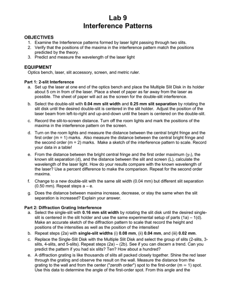
Lab 9 Interference Patterns OBJECTIVES 1. Examine the Interference patterns formed by laser light passing through two slits. 2. Verify that the positions of the maxima in the interference pattern match the positions predicted by the theory. 3. Predict and measure the wavelength of the laser light EQUIPMENT Optics bench, laser, slit accessory, screen, and metric ruler. Part 1: 2-slit Interference a. Set up the laser at one end of the optics bench and place the Multiple Slit Disk in its holder about 5 cm in from of the laser. Place a sheet of paper as far away from the laser as possible. The sheet of paper will act as the screen for the double-slit interference. b. Select the double-slit with 0.04 mm slit width and 0.25 mm slit separation by rotating the slit disk until the desired double-slit is centered in the slit holder. Adjust the position of the laser beam from left-to-right and up-and-down until the beam is centered on the double-slit. c. Record the slit-to-screen distance. Turn off the room lights and mark the positions of the maxima in the interference pattern on the screen. d. Turn on the room lights and measure the distance between the central bright fringe and the first order (m = 1) marks. Also measure the distance between the central bright fringe and the second order (m = 2) marks. Make a sketch of the interference pattern to scale. Record your data in a table! e. From the distance between the bright central fringe and the first order maximum (y1), the known slit separation (d), and the distance between the slit and screen (L), calculate the wavelength of the laser light. How do your results compare with the known wavelength of the laser? Use a percent difference to make the comparison. Repeat for the second order maxima. f. Change to a new double-slit with the same slit width (0.04 mm) but different slit separation (0.50 mm). Repeat steps a – e. g. Does the distance between maxima increase, decrease, or stay the same when the slit separation is increased? Explain your answer. Part 2: Diffraction Grating Interference a. Select the single-slit with 0.16 mm slit width by rotating the slit disk until the desired singleslit is centered in the slit holder and use the same experimental setup of parts (1a) – 1(d). Make an accurate sketch of the diffraction pattern to scale that record the height and positions of the intensities as well as the position of the intensities! b. Repeat steps (2a) with single-slit widths (i) 0.08 mm, (ii) 0.04 mm, and (iii) 0.02 mm. c. Replace the Single-Slit Disk with the Multiple Slit Disk and select the group of slits (2-slits, 3slits, 4-slits, and 5-slits). Repeat steps (2a) – (2b). See if you can discern a trend. Can you predict the pattern if you had six slits? Ten? How about a hundred? e. A diffraction grating is like thousands of slits all packed closely together. Shine the red laser through the grating and observe the result on the wall. Measure the distance from the grating to the wall and from the center ("zeroth order") spot to the first-order (m = 1) spot. Use this data to determine the angle of the first-order spot. From this angle and the f. wavelength of the laser, calculate the number of slits per centimeter for the diffraction grating. Predict how the spot pattern will change if you use a green laser instead of red. Remember that the wavelength of green light is smaller than that of red light. Shine a green laser through the grating. Was your prediction correct? What would you predict if you had a blue laser? Or a yellow one? How about magenta? Part 3: Thin Film Interference The object is to determine the thickness of a human hair by observing how many interference fringes are formed when it is placed between two interference plates. a. Set up the apparatus with the help of the instructor. A large mercury lamp (546 nm) is used to illuminate the interference plates. b. Place a human hair near one end between the upper and lower interference plates and observe the fringes. Move rubber bands around until fringes are as straight as possible. It helps to put the one rubber band a little towards the center from the hair rather than on the end. c. Sketch a diagram and explain why interference patterns are observed. d. Count the dark fringes between the hair and the point of contact between the two plates by determining the fringe density, that is, the number of dark fringes per centimeter. Then the total number of m fringes is m distance from the hair to the point of contact fringe density e. To determine the thickness of the hair, calculate t 21 m


