pe_2tap_dml.doc
advertisement

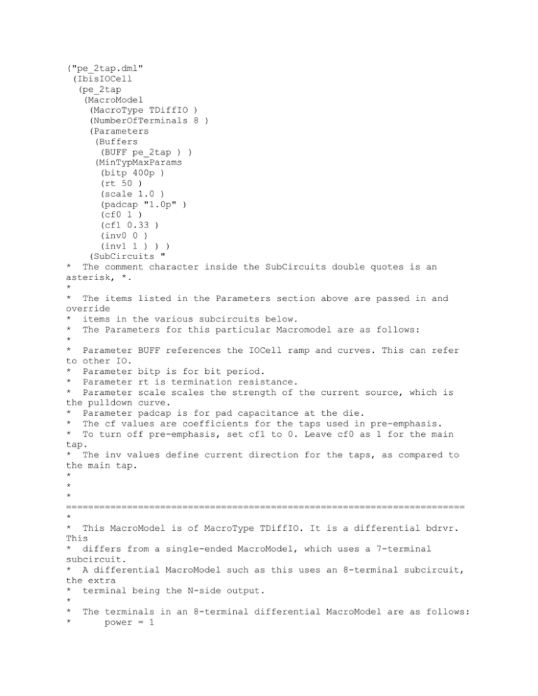
("pe_2tap.dml" (IbisIOCell (pe_2tap (MacroModel (MacroType TDiffIO ) (NumberOfTerminals 8 ) (Parameters (Buffers (BUFF pe_2tap ) ) (MinTypMaxParams (bitp 400p ) (rt 50 ) (scale 1.0 ) (padcap "1.0p" ) (cf0 1 ) (cf1 0.33 ) (inv0 0 ) (inv1 1 ) ) ) (SubCircuits " * The comment character inside the SubCircuits double quotes is an asterisk, *. * * The items listed in the Parameters section above are passed in and override * items in the various subcircuits below. * The Parameters for this particular Macromodel are as follows: * * Parameter BUFF references the IOCell ramp and curves. This can refer to other IO. * Parameter bitp is for bit period. * Parameter rt is termination resistance. * Parameter scale scales the strength of the current source, which is the pulldown curve. * Parameter padcap is for pad capacitance at the die. * The cf values are coefficients for the taps used in pre-emphasis. * To turn off pre-emphasis, set cf1 to 0. Leave cf0 as 1 for the main tap. * The inv values define current direction for the taps, as compared to the main tap. * * * ======================================================================== * * This MacroModel is of MacroType TDiffIO. It is a differential bdrvr. This * differs from a single-ended MacroModel, which uses a 7-terminal subcircuit. * A differential MacroModel such as this uses an 8-terminal subcircuit, the extra * terminal being the N-side output. * * The terminals in an 8-terminal differential MacroModel are as follows: * power = 1 * outp = 2 * ground = 3 * input = 4 * enable = 5 * power_clamp_reference = 6 * ground_clamp_reference = 7 * outn = 8 * * ======================================================================== * * This is the top-level subcircuit for this MacroModel. * It MUST have the same name as the IOCell, or it will not work. .subckt pe_2tap nvdd outp ngnd in en pcl gcl outn BUFF=BUFF ibis_file=ibis_models.inc + bitp=400p + rt=50 + scale=1 + padcap=1p + cf0=1 cf1=1 + inv0=0 inv1=1 * A VCVS is derived for the N side stimulus. einn inn ngnd v='1 - v(in, ngnd)' * P side driver subcircuit call xp nvdd outp ngnd in en main_driver BUFF=BUFF ibis_file=ibis_file + bitp=bitp + rt=rt + scale=scale + padcap=padcap + cf0=cf0 cf1=cf1 + inv0=inv0 inv1=inv1 * N side driver subcircuit call xn nvdd outn ngnd inn en main_driver BUFF=BUFF ibis_file=ibis_file + bitp=bitp + rt=rt + scale=scale + padcap=padcap + cf0=cf0 cf1=cf1 + inv0=inv0 inv1=inv1 * Here is the main single-ended driver subcircuit, called main_driver. .subckt main_driver nvdd out ngnd in en + bitp=400p + rt=50 + scale=1 + padcap=1p + cf0=1 cf1=1 + inv0=0 inv1=1 * Internal termination resistor and pad capacitance elements. r nvdd out 'rt' c out ngnd 'padcap' * Here are the subcircuit calls for the tap inputs, using subcircuit delayin. xin0 in0 in ngnd delayin inv=inv0 xin1 in1 in ngnd delayin inv=inv1 del='bitp' * Here are the calls for the here_is_a_tap subcircuits, which contain the taps. xtx0 nvdd out ngnd in0 en here_is_a_tap scale='scale * cf0' c_comp=0 xtx1 nvdd out ngnd in1 en here_is_a_tap scale='scale * cf1' c_comp=0 * This is the subcircuit definition for here_is_a_tap, used for the taps. .subckt here_is_a_tap nvdd out ngnd in en scale=1 c_comp=0 bdrvr nvdd out ngnd in en Model=BUFF File=ibis_file c_compX=c_comp VIScale_pulldown='scale' VIScale_groundclamp=0 .ends here_is_a_tap * The delayin subcircuit drives the inputs to the here_is_a_tap subcircuit. * The main tap is always on, and has inv=0. The other tap is the boost tap, and has inv=1. .subckt delayin in1 in ngnd inv=0 del=0 * A voltage source e_ctrl is defined from node in2 to ngnd. If you look at the expression for * e_ctrl, you can see that if inv=1, then its value is always 1-v[in], or exactly opposite the * 0 or 1 stimulus that is initially fed in. So, for inv=1 case, * * if v[in] = 0, e_ctrl then = 1 * If v[in] = 1, e_ctrl then = 0 * * And when inv=0, e_ctrl simply mimics v[in]. * e_ctrl in2 ngnd v='inv * (1 - v(in,ngnd)) + (1-inv) * v(in,ngnd)' * The voltage source ein1 directly drives the main and boost taps. It is equal to e_ctrl, * but is delayed by delay=del. For the main driver the delay=0, and for the boost driver delay=bitp. * So the input to the boost tap ends up being * * opposite that of the main tap * scaled down by cf1 * delayed by one bit period * * which is what models the pre-emphasis effect. ein1 in1 ngnd pwl in2 ngnd delay=del datapoints vv 0 0 1 1 end vv .ends delayin .ends main_driver .ends pe_2tap " ) ) (Model (ModelType Output ) ) (PowerClamp (ReferenceVoltage (maximum 1.5 ) (minimum 1.5 ) (typical 1.5 ) ) ) (GroundClamp (ReferenceVoltage (maximum 0 ) (minimum 0 ) (typical 0 ) ) ) (PullDown (ImpedanceClass (High minimum ) (Low maximum ) (Typical typical ) ) (ReferenceVoltage (maximum 0 ) (minimum 0 ) (typical 0 ) ) (VICurve "-1.5 -0.05 -0.04 -0.06 0.0 0.0 0.0 0.0 0.1 0.008 0.007 0.009 0.2 0.014 0.013 0.015 0.3 0.015 0.014 0.016 1.0 0.016 0.015 0.017 2.0 0.017 0.016 0.018 3.0 0.018 0.017 0.019" ) ) (PullUp (ReferenceVoltage (maximum 1.5 ) (minimum 1.5 ) (typical 1.5 ) ) ) (Ramp (Fall (maximum (dt 40p ) ) (minimum (dt 60p ) ) (typical (dt 50p ) ) ) (Rise (maximum (dt 40p ) ) (minimum (dt 60p ) ) (typical (dt 50p ) ) ) ) (Notes "This example MacroModel was provided by CADENCE DESIGN SYSTEMS, INC. to facilitate the work of the IBIS MacroModel Committee. The original template for this model was developed by Dr. C. Kumar." ) ) ) (LibraryVersion 136.2 ) )


