CS 4850: CS Senior Project SRS - OOA Modeling Components
advertisement

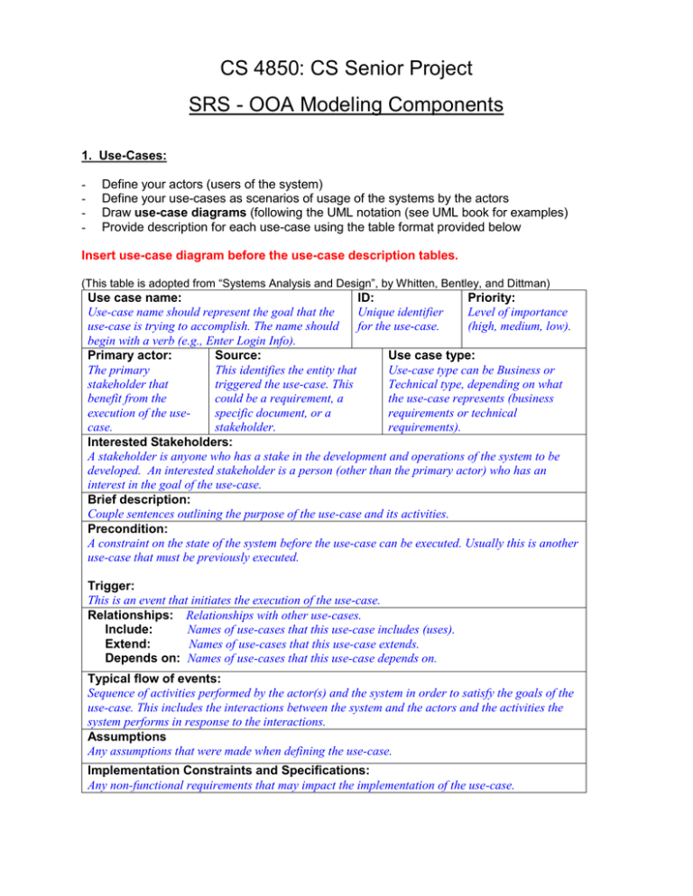
CS 4850: CS Senior Project SRS - OOA Modeling Components 1. Use-Cases: - Define your actors (users of the system) Define your use-cases as scenarios of usage of the systems by the actors Draw use-case diagrams (following the UML notation (see UML book for examples) Provide description for each use-case using the table format provided below Insert use-case diagram before the use-case description tables. (This table is adopted from “Systems Analysis and Design”, by Whitten, Bentley, and Dittman) Use case name: ID: Priority: Use-case name should represent the goal that the Unique identifier Level of importance use-case is trying to accomplish. The name should for the use-case. (high, medium, low). begin with a verb (e.g., Enter Login Info). Primary actor: Source: Use case type: The primary This identifies the entity that Use-case type can be Business or stakeholder that triggered the use-case. This Technical type, depending on what benefit from the could be a requirement, a the use-case represents (business execution of the usespecific document, or a requirements or technical case. stakeholder. requirements). Interested Stakeholders: A stakeholder is anyone who has a stake in the development and operations of the system to be developed. An interested stakeholder is a person (other than the primary actor) who has an interest in the goal of the use-case. Brief description: Couple sentences outlining the purpose of the use-case and its activities. Precondition: A constraint on the state of the system before the use-case can be executed. Usually this is another use-case that must be previously executed. Trigger: This is an event that initiates the execution of the use-case. Relationships: Relationships with other use-cases. Include: Names of use-cases that this use-case includes (uses). Extend: Names of use-cases that this use-case extends. Depends on: Names of use-cases that this use-case depends on. Typical flow of events: Sequence of activities performed by the actor(s) and the system in order to satisfy the goals of the use-case. This includes the interactions between the system and the actors and the activities the system performs in response to the interactions. Assumptions Any assumptions that were made when defining the use-case. Implementation Constraints and Specifications: Any non-functional requirements that may impact the implementation of the use-case. 2. Class Description: - Apply the CRC method (described in chapter 21 handout) to your use-cases to identify your classes Draw conceptual UML class inheritance diagram (see UML book for examples) For each class provide a description using the table format below Insert class diagram before the class description tables. Class name: The class name Brief description: Brief description of the class Attributes (fields) Attribute Description Attribute 1 Brief description of attribute 1 Attribute 2 Brief description of attribute2 ... ... Methods (operations) Method Description Method 1 Brief description of method1 1 Method 2 Brief description of method 2 ... ... 3. Sequence Diagrams: - Draw a UML sequence diagram for each use-case. Multiple diagrams may be drawn for a use-case (See Chapter 8 and lecture slides, part II, Sequence diagram) 4. Object collaboration Diagram: - Draw UML object relationship (collaboration) diagrams (See Chapter 8 and lecture slides, part II, Object Relationship Modeling) 5. State Transition Diagram: - Draw UML state diagrams for the system (See Chapter 8 and lecture slides, part II, STD and Event Flow diagram)

