TEXAS HURRICANE ARF ASSEMBLY MANUAL
advertisement
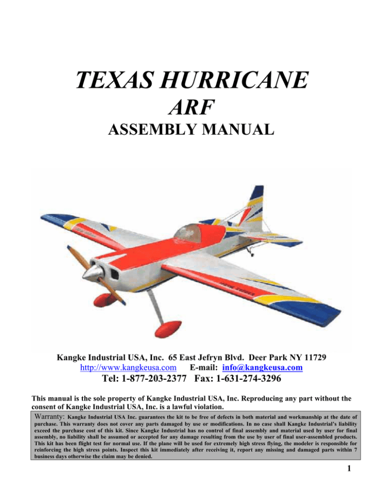
TEXAS HURRICANE
ARF
ASSEMBLY MANUAL
Kangke Industrial USA, Inc. 65 East Jefryn Blvd. Deer Park NY 11729
http://www.kangkeusa.com
E-mail: info@kangkeusa.com
Tel: 1-877-203-2377 Fax: 1-631-274-3296
This manual is the sole property of Kangke Industrial USA, Inc. Reproducing any part without the
consent of Kangke Industrial USA, Inc. is a lawful violation.
Warranty: Kangke Industrial USA Inc. guarantees the kit to be free of defects in both material and workmanship at the date of
purchase. This warranty does not cover any parts damaged by use or modifications. In no case shall Kangke Industrial’s liability
exceed the purchase cost of this kit. Since Kangke Industrial has no control of final assembly and material used by user for final
assembly, no liability shall be assumed or accepted for any damage resulting from the use by user of final user-assembled products.
This kit has been flight test for normal use. If the plane will be used for extremely high stress flying, the modeler is responsible for
reinforcing the high stress points. Inspect this kit immediately after receiving it, report any missing and damaged parts within 7
business days otherwise the claim may be denied.
1
Congratulations!
Kangke Industrial USA, Inc. brings you one of the finest ARF HURRICANE models available. Skilled
craftsmen combined with top grade materials and precision jigs have all come together to produce an
aircraft with outstanding flight qualities. If you follow the directions carefully the performance of this
aircraft will surely please you.
WARNING! As model aircraft get larger and more powerful, the risk for injury increases. Kangke’s
extensive testing procedures insure a high quality kit that has gone through many steps to provide you
with a safe reliable airframe. Nothing we can do however will make up for poor assembly or irresponsible
behavior at the field. A model of this size traveling at 80 MPH contains enough energy that if it were to
contact another person, the injuries would be extensive possibly fatal. The safe operation of this model is
your responsibility and yours alone. If you are a beginner or have never flown a model of this size and
power, you should not make the attempt without the help of an experienced pilot.
Specifications:
Length
Wing Span
Wing Area Wet
Surface Area
Weight
Engine (Glow)
(Gas)
Kit Contents:
70 in.
78 in.
1062sq. in.
1355sq. in.
11.5-14.5
lbs.
140-210
2.10-3.4
Fuselage
Wing panel
Ailerons
Cowling
Canopy
Main Gear
Stabilizer
Elevator
Fin
Rudder
Servo mount
1
2
2
1
1
1
1
2
1
1
1
Fuel tank
Wheels
Tail gear
Tail wheel
Control horn
1
2
1
1
6
Motor mount
Hardware pack
1
1
Manual
Wheel pants
1
1
If you are familiar with the assembly of ARF type airplanes, you will find the following assembly
sequence to be unusual. The sequence was designed to speed assembly. The hurricane was designed as
a competition aircraft, capable of being shipped to and from events. Because of some of the special
features found in the Hurricane, like the removable tail assembly, the build up may seem out of order.
Please follow the assembly instructions as written. The hurricane will take approximately 20-25 hours
to complete.
The following additional items will also be needed to build the HURRICANE
Masking tape
HOUSEHOLD ITEMS:
HOBBY ITEMS:
Ruler
4 oz. 30 min. epoxy
Radio 4-channel min.
Felt tip pen
Popsicle sticks
5-6 servos
Screw drivers
Hobby knife
Control rods
Pliers
Thin CA .5 oz.
Fuel line 20-inches
Wax paper
Med. CA 1 oz.
Motor
5/32 drill
Paper towels
Muffler
1/8 drill
Alcohol
Read each step of the instructions carefully. Be sure you understand what is required and what the
procedure is before you glue or cut anything. How well you assemble this model will have a direct effect
on its flight characteristics.
2
TAIL ASSEMBLY
Install the stabilizer hold down plate with epoxy.
Center it carefully and allow to cure.
supports. The two holes should be ½-inch in from
the hinge line, 3 ½-inches apart and 2 ½-inches
down from the fin top. This will place them in the
center of the horizontal support in the fin.
Measure and locate the exact center of the
stabilizer. Using a felt tip pen draw a line on
center.
Shine a strong light through the stabilizer and
locate the two holes at each end for the flying wire
supports and the center holes for the hold down
plate. Open the holes with a pin.
Carefully line up the rudderpost. Slide the
stabilizer in position with the centerline in the
middle of the rudder slot.
Insert a pin in the center of the turtle deck at the
top of the fuselage. Move the string from one
corner of the stabilizer to the other until it is square
with the fuselage and the line is still in the center of
the rudder slot.
With a felt tip marker, trace the outline of the
fuselage on the top of the stabilizer.
Drill the two holes in the fin for the flying wire
3
Using a sharp razor knife, carefully slice through
the covering on the top of the stabilizer about ¼inch inside the lines. Try not to slice into the wood,
as this would weaken the structure. Peel away the
covering.
Cover the stabilizer-mating surface with a thin
layer of epoxy.
STABILIZER OPTIONS
If you wish the stabilizer may be attached without
removing the covering. This will make shipping
easier if that is in your future plans. To do this skip
the following sequence, bolt the stabilizer in place
with the hold down screws, cover with wax paper
and proceed to the rudder installation.
Cover the fuselage-mating surface with wax paper
to prevent the excess epoxy from gluing the
stabilizer support to the fuselage. Assemble the
stabilizer and its mating surface using the drawn
lines for alignment. Install on the wax paper
covered fuselage and carefully line up the tail post.
Verify the alignment with the string as before and
allow curing. Clean the excess epoxy with a paper
towel moistened with alcohol.
Carefully insert the rudder/tail-post. As was done
with the stabilizer mark the outline of the fuselage
with a felt tip pen.
Cut the covering as before ¼-inch below the line
and remove.
4
Install the two stabilizer lock down screws with
knurled nuts. Bend the flying wire mounts to 45degrees and install as shown.
Install the flying wire bracket on the fuselage
bottom. The bracket should be 5 ½-inches forward
If the removable stabilizer option is used cover the
top of the stabilizer with wax paper before
proceeding.
With the wax paper still in place coat the inside of
the rudder slot with epoxy and slide the rudder
forward until the rudder post is against the back of
the fuselage with the post pins engaged. Allow to
cure.
fr
om the fuselage back edge. Install the lower flying
wires. Use the knurled nuts to lock the
cle
vises in place. The flying wires are adjusted so all
endplay is gone, but not tight enough to flex the
stabilizer.
5
Install the upper flying wires. Once again only
make them tight enough to eliminate all endplay.
No knurl nuts are used on the top wires.
MOTOR INSTALATION
LANDING GEAR
Slide the axle through the deep offset in the wheel,
Install the wheel spacer followed by the regular
nut.
The following instructions show the installation of
the BRISON AIRCRAFT 2.4 engine.
{www.brisonaircraft.com 972 241 9152}
Because of the 1 ½-degrees of right thrust built into
the engine support follow the instructions to be
sure the spinner lines up correctly with the cowl.
Locate the crankshaft horizontal centerline by
measuring 2 ¼ inches up from the bottom of the
engine support. Locate the vertical centerline 1/4inches to the LEFT of the engine support center.
The main gear has a front and back, when installed
correctly the gear will have a forward sweep. Using
the supplied screws install the gear on the fuselage.
The back of the spinner should be no less than 5
5/8-inches from the engine support. The BRISON
2.4 used in the prototype required a ¾-inch spacer
made from hard wood.
Using the small screw, two flat washers and a
6
locking nut, install the wheel pant on the gear.
Slide the assembled wheel/axle through the large
hole and secure with the locking nut. Adjust the
two nuts on the axle to make sure the wheel rotates
freely.
TAIL WHEEL
Install the wheel on the gear wire with a collar as
shown. Slide the assembly up through the tail
wheel bracket into the long collar and secure with a
set-screw.
Epoxy the guide tube into the bottom of the rudder,
be sure not to get epoxy inside the tube. Install the
bracket as shown in the photo, be sure the bracket
does not cover the rudderpost. Slide the tiller arm
into the rudder guide tube, then slide the rudder
over its hinges engaging the long collar at the same
time.
HINGES
Carefully align the rudder then apply one drop of
thin CA to each side of the rudder hinges. Repeat
this for all the remaining control surfaces [wing &
elevator].
SERVOS
Because of the size and weight of the TEXAS
HURRICANE standard servos do not produce
enough torque for high performance aerobatics or
3-D flight. The following are the torque
requirements for this level of performance as well
as the servos used in the prototype.
Ailerons:
50 oz-in. prototype used HITEC
HS-625MG
Elevators:
60 oz-in. prototype used HITEC
HS-625MG
Rudder:
100 oz-in. prototype used HITEC
HS645MG
Throttle:
Standard servo HITEC HS425BB
CAUTIONS: Gas engines because of the ignition
systems require some special care. The ignition is
capable of producing radio interference that can
shorten the range of the radio gear.
To help minimize these problems use the following
recommendations: Never use a solid wire for
throttle control, use Nyrod or other plastic
nonconductor. Keep all radio gear at least 12
inches from all ignition components, such as
battery, switches, wiring and the unit itself. All
servo extensions should have at least 10 twists per
foot, this helps reduce their ability to act as
antenna. If a servo is used to operate the ignition
on/off switch, do not mount the switch at the servo,
instead use a piece of Nyrod and a remote switch
bracket. Be sure spark plug wires are shielded and
the shield is properly grounded to the engine.
Follow the engine manufactures instructions. Large
7
powerful servos have a higher power consumption
rate than standard servos, for this reason it is
important the battery selected be capable of
supplying the required amperage. In the prototype
we used we used the HITEC #57404 1100ma. The
switch harness must also be of the heavy-duty type;
a lightweight switch may overheat and fail under
high loads.
OPTIONAL REAR RUDDER SERVO
The BRISON 2.4 engine used in the prototype
balances well with pull-pull rudder control. If the
motor you select weighs more you may wish to
install the rudder servo in the bottom of the rear of
the fuselage. This will help compensate for the
additional weight. Use this procedure only if
weight will be a problem. If weight is not a
problem skip this step and proceed to STANDARD
PULL-PULL SERVO.
Cut the supplied clear plastic tube in two pieces
approximately 6 ¾-inches long. Epoxy the tube in
place after roughening the last inch to promote
good adhesion. The guide tube should pass through
the fuselage bulkhead in front of the servo well.
The front of the guide tube does NOT get glued.
REAR RUDDER SERVO
Open a hole in the fuselage bottom just forward of
the flying wire bracket. Fabricate hardwood
mounts and epoxy them in the fuselage. The servo
may be recessed into the fuselage to match your
servo. Install the servo following the manufacture
instructions. With this configuration either pullpull or push rod control may be used. Pull-pull is
more precise and the preferred method.
Mount the rudder servo using the manufacture
instructions. The servo control horn should be at
least 2 ¼-inches from outside hole to outside hole.
STANDARD PULL-PULL RUDER SERV0
Drill a 3/16-inch hole in the fuselage side, 4-inches
forward of the rudder hinge line 3 ¼-inches down
from the bottom of the stabilizer. Using a small
hand file angle the hole to the path the pull-pull
wire will exit as shown.
8
others like to use a clevis. Use the system you are
most comfortable with.
Remove the covering from the exit slots in the
servo bay doors.
Mount the elevator servos on the servo bay doors.
Pre drill the screw holes to prevent the rails from
splitting. If your radio does not support two
elevator servos, it will be necessary to use a “Y”
harness. It will also be necessary to either reverse
one servo or use a servo reverser available from
your local hobby store.
Locate the longest of the control horns as well as
the threaded rod. Use these for the rudder.
Install the elevator servo bay doors with the four
provided screws.
Drill a hole ¼-inch back from the outside edge of
the rudder bevel 1 3/8-inchs up from the bottom.
Install the two longest control horns joined by the
threaded rod. Fabricate the pull-pull cables and
install. Some like to solder the cables, others like to
use the crimp method. At the servo end some like
to loop the cable through the control horn while
9
Repeat the procedure with the wing servos. Pre
drill the servo screw holes and open the control
horn slot.
Use the pull string to work the servo extension
through the wing and out the exit hole in the root
rib.
CONTROL RODS
Using a control horn back plate, line up the edge
with the top of the elevator bevel 5/8-inch out from
the inside corner of the elevator. Drill a hole at this
location.
Install the elevator control horn using a screw,
backing plate and a control link. The elevators get
the mid size horns.
Be sure the servo is centered and the elevator
neutral. Measure and fabricate a control rod. For
sport flying 2-56 rods will work, but for the loads
required for advanced aerobatics 4-40 rods are
recommended.
Install the wing servos with the provided screws.
10
Open holes
Install the aileron control horn just as was done
with the elevator. Be sure the control rod will be in
a straight line to the rear. Fabricate the control rod
as was done before.
FUEL TANK
Because the motor and carburetor are completely
enclosed by the cowling it will be necessary to ad
a fill/drain line to eliminate the need to remove
the cowl to refuel the aircraft.
Insert the three tubes through the rubber stopper.
Install the inner and outer cap plates and the
center screw, do not tighten the screw. Slide the
long and one short tube in allowing 3/8-inch to
protrude to the outside. The second short tube
[fill/drain] should be 1/8-inch beyond the inner
plate. Bend the long tube as shown to the tank
top. Insert the flop weight in the end of the
supplied flop tube. Cut the flop tube just short
enough so the flop weight cannot touch the tank
end when assembled. Lube the rubber stopper
lightly with cooking oil, align the vent tube with
the tank top and carefully insert into the tank.
Tighten the screw just enough to expand the
stopper and seal the tank.
Open the holes in the side of the fuselage for the
servo wires and wing lock screw.
Pass the servo wires through the hole, install the
wings and lock screws.
Locate and install the throttle servo where the push
rod will not interfere with the lock screw or the
11
wing servo wires.
Fabricate and install the throttle control rod. Be
sure the throttle will open and close all the way
without binding the servo.
CANOPY
Trim the canopy carefully along the scribed lines.
Sand the edge smooth; be careful not to scratch the
surface.
Detail the pilot compartment to the level desired.
Locate the canopy for best fit; tape securely. Drill
two 1/8-inch holes in each side of the canopy only
then secure with the supplied screws. Remove the
screws and harden the threads with CA. An
alternative method, if you don’t want the canopy
removable, it may be glued on using canopy
adhesive. Additional trim may be added as desired.
If you engine requires ignition and battery now is
the time to install them. Install the engine cut-off
switch as directed by the engine manufacture.
Install the fuel tank. Use the supplied wood
supports, leave enough room to surround the tank
with foam rubber.
Install fuel lines and all other engine accessories.
Carefully add any openings the cowl may require
for cooling and adjustments. Mount the cowl using
the supplied screws.
12
make large changes in stability. For your first
flights we recommend using a balance point at
the forward end of the center of gravity {C.G.}
range, this location will provide the most
stability. As your comfort and skill increase
slowly move the C.G. aft to increase the control
response.
The recommended starting range for the C.G. is 4
3/4 inches to 5 1/4 inches back from the leading
edge of the wing measured against the side of the
fuselage.
Mount the radio receiver and switch as directed by
the manufacture. Install the antenna. Install the
canopy / top cover.
At this point its time to prepare for final assembly.
All radio equipment except the battery should be
installed as per the manufacture instructions. The
location of the battery may be used to aid in final
balance.
FINAL ASSEMBLY
Additional paint and exterior trim such as decals
and numbers may be added. Whatever details you
add keep in mind that weight is the enemy of a
high performance aircraft KEEP IT LIGHT.
WEIGHT AND BALANCE
Nothing affects the way a plane flies more than
weight and balance. Failure to perform this
procedure may result in an aircraft that is at
best difficult to control and at worst impossible
to fly. Even small changes in the balance point
Turn the aircraft upside down and support it at that
location. Because of the mid-wing configuration it
is very difficult to get the plane to balance, be
patient you can do it. Slide the battery pack to a
position where the plane will balance level. Mount
the battery inside the fuselage at the determined
location.. Reinstall the wing and check the C.G.
again. If necessary add weight to the nose or tail.
CONTROL THROWS
With your radio on, center all trims and adjust
the clevises so all control surfaces are straight.
Measure the control surface movement at the
widest part of each surface. Use the servo horns
and bell crank holes to adjust the control throw.
For your first flights the control throws should
be set to the following:
Elevator 5/8-inch up / down
Rudder 1 1/4- inch right / left
Aileron 3/8-inch up / down
Double check all controls move in the proper
direction.
13
MOTOR SET UP
Be sure the motor is properly broken in using the
manufacture instructions. Set the throttle throw to
shut the motor off when the trim is pulled down
and idles reliably with the trim up.
After the motor is set, run one tank of gas at full
throttle, measure how much time it takes to run the
tank dry.
CONGRADULATIONS you are now ready for
test flights.
Before leaving for the field be sure your batteries
are fully charged and you have all the required
support equipment {fuel, starter, glow driver, etc.}.
Although the HURRICANE will fly well in wind,
wait for a nice day.
At the field have a helper hold the airplane,
following the radio manufactures instructions
perform a range check of the radio. Do this with
the motor off, start the motor and do it again.
Perform this test EVERY TIME YOU GO TO FLY!
TRIMING BASIC FLIGHT
The HURRICANE is NOT a trainer. A true
aerobatic aircraft, it goes only where you point
it and will not recover to level flight without
control input. If you do not have high
performance experience seek the help of
someone who does.
Line up on the center of the runway and slowly
open the throttle, using the rudder to maintain
directional control. Once the tail is up apply a little
up elevator and allow the plane to gently lift off the
runway. Keep the climb angle and turns shallow
until you reach a safe altitude. Reduce the throttle
to about 60% power. With the airplane flying away
from you adjust the radio aileron trim tab till the
wing stays level. Turn and line up the plane with
the runway. Adjust the elevator trim till the plane
maintains level flight. Once again with the airplane
flying away from you adjust the rudder trim till the
fuselage tracks straight {it may be necessary to
correct the aileron trim after this procedure}.
Continue to fly and trim until the aircraft is
tracking well, land before the fuel runs out. Carry a
little power on final approach until over the end of
the runway, then cut power to idle, hold the plane
just off the runway till the airspeed bleeds off and
the plane settles on. If the landing is too long add
power go around and try again, don’t try to force it
to the ground.
Now its time to zero out the trims. To do this
measure the control location, center the trim tab
on the radio and adjust the servo horn for large
changes, the control clevis for small changes.
For example if after the flight the rudder is 3/16
inch to the right, center the radio trim and
adjust the clevis till the rudder once again
measures 3/16 right. By doing this whenever you
fly, setting the radio trims at center will result in
a well-trimmed plane. Increase the control
travel, as you become more familiar with the
flight characteristics until loops take about 50
feet and knife edge can be maintained with 80%
stick deflection. Final roll rate should be 300360 degrees per second.
If you have followed the procedures in this
Manuel you will now be rewarded with one of
the finest flying sport models available. All
primary aerobatic maneuvers are at your
fingertips and the aircraft will perform them
with ease. No further trim work will be required
until you are ready for unlimited and advanced
3-D flight. Before attempting any of the
ADVANCED FLIGHT TRIM procedures you
must be completely comfortable with inverted
and knife-edge flight. The following trim
sequence is very time consuming and you may
not be able to complete it in one day. Every
change made during this procedure will affect
all others so it will be necessary to start the
procedure from the beginning after each
adjustment.
ADVANCED FLIGHT TRIM
All the following tests should be performed at
80% power unless noted.
C.G. Fine Tuning:
14
Roll inverted, neutral elevator to two clicks of
down trim, if the model descends move the C.G.
aft. If the model climbs move the C.G. forward.
C.G. movement should be no more than ¼-inch
at a time.
Engine Thrust Angle Right/Left:
On a low pass 50% power directly into the
wind, go to 80% power and pull to a vertical
line at the same time. As the model slows do not
correct the path with rudder. If the model yaws
right add 1/16-inch shims under the right side
motor mount bolts at the firewall. If the model
yaws left place the shims under the left side.
Main Wing Incidence:
Roll to knife-edge flight, if down elevator is
required to maintain a straight line, shim the back
of the main wing 1/8-inch at a time till the elevator
is neutral. If up elevator is required shave the rear
of the wing saddle 1/8-inch at a time.
Engine Thrust Angle Up/Down:
On a low pass 50% power crosswind, go to 80%
power and pull vertical at the same time. As the
model slows do not correct path with elevator.
If the model tries to loop add 1/16-inch shims to
the top motor mount bolts. If the model tries to
push over to the wheel side, add 1/16-inch shims to
the lower motor mount bolts.
Wing Tip Weight:
Level flight into the wind, roll inverted neutral
aileron. If one wing drops add weight to the other
wing tip 1/8-once at a time.
Elevator Surface Alignment:
Fly away from you directly into any wind, apply
full throttle and pull two consecutive loops. Model
rolls right, raise left elevator, model rolls left, raise
right elevator.
15
