7 DAMAGE TO INDUSTRIAL FACILITIES
advertisement

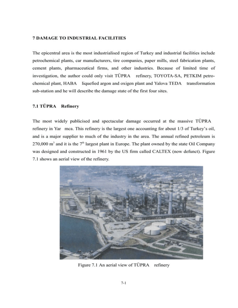
7 DAMAGE TO INDUSTRIAL FACILITIES The epicentral area is the most industrialised region of Turkey and industrial facilities include petrochemical plants, car manufacturers, tire companies, paper mills, steel fabrication plants, cement plants, pharmaceutical firms, and other industries. Because of limited time of investigation, the author could only visit TÜPRA chemical plant, HABA refinery, TOYOTA-SA, PETKIM petro- liquefied argon and oxigen plant and Yalova TEDA transformation sub-station and he will describe the damage state of the first four sites. 7.1 TÜPRA Refinery The most widely publicised and spectacular damage occurred at the massive TÜPRA refinery in Yar mca. This refinery is the largest one accounting for about 1/3 of Turkey’s oil, and is a major supplier to much of the industry in the area. The annual refined petroleum is 270,000 m3 and it is the 7th largest plant in Europe. The plant owned by the state Oil Company was designed and constructed in 1961 by the US firm called CALTEX (now defunct). Figure 7.1 shows an aerial view of the refinery. Figure 7.1 An aerial view of TÜPRA 7-1 refinery The refinery is located along the shore at Tütünçiftlik of the western Kocaeli province. The ground is firm and no ground failure occurred except some liquefaction at re-claimed land during the earthquake. The refinery has three crude oil and three vacuum distillation unitsö three hydrodesulphurisation (kero-diesel) units, one hydrocracker, two unifer/reformer units, two FCC units, one isomerization unit, one asphalt unit, one sulphur recovery unit, one isopentane unit, one naphtha sweeteneing unit and related utility units. The products are naphtha, gasoline, jet-oil and kerosene. The 860,000-ton crude oil is stored in 14 large cylindrical tanks and 840,000 ton semi-products are stored in 86 middle and small size cylindrical tanks. Figure 7.2 shows the damaged and burned tanks locations. Figure 7.2 Locations of damaged and burned tanks 7-2 7.1.1 Damage State of Refinery (1) Fire at Tanks with Floating Roofs 6 cyclindrical tanks having floating roofs burned due to the earthquake. Out of 6 tanks, 4 middle size tanks has a diameter of 20-25 m and 2 small size tanks has a diameter of 10 m. Naphtha in the middle size tanks were completely burned. Tanks were damaged as a result of thermal deformation. The estimated naphtha is about 36,000 ton. Figures 7.3 and 7.4 show the deformed state of burned tanks. The fire in a Naphtha tank farm was considered to be initiated by sparks created by bouncing of the floating roof in one of the tanks during the earthquake. The sparks ignited the Naphtha. There are 46 tanks with floating roofs and they were damaged independent of the size of tanks. They are now being repaired. Most of tanks were built in 1961 according to the earthquake design code of California for a Level 4 earthquake shaking. In addition to cylindrical tanks, there are some spherical tanks in the plant. None of these was damaged. As seen in Figure 7.5, the piers and bracing of these spherical tanks shows no visible damage. Therefore, they should have had enough resistance against the ground shaking during the earthquake. The sealing of the tanks with the floating roof built in 1961 was mainly metallic. There were no damage to joints of pipes except to those damaged by the fire in contrast to the heavy damage to joints of piping as a result of liquefaction in MC terminal during the Hyogoken Nanbu earthquake. Only one tank showed buckling of elephant foot type. This was a water storage tank. As seen in Figure 7.6, the upper part of a tank with a fixed roof near a burned tank was deformed as a result of pressure caused by heating rather than sloshing. 7-3 Figure 7.3 Burned cyclindrical tank Figure 7.4 Burned cyclindrical tank 7-4 Figure 7.5 Undamaged spherical tank Figure 7.6 Deformation of a cyclindrical tank with a fixed roof 7-5 (2) Fire due to Collapsed Heater Stack The collapse of one of crude oil stacks with a height of 105m caused the crude oil unit fire. The temperature of the collapsed part was more than 500 0C. Figure 7.7 and 7.8 shows the burned crude oil unit and collapsed heater stack. The height of heater stack ranges from 90m to 115m and there are 5 heater stack in the plant. The collapsed heater stack was 105m high. The heater stacks were built in 1981. The reason of collapse of the heater stack may be associated with material degradation as a result of corrosion due to alkali gases. It is difficult to consider that the main cause of the collapse of the stack is ground shaking only. Both fires started soon after the earthquake. The fire of the crude oil unit extinguished at the night of August 17. While extinguishing the fire at the crude oil unit, the fire in the tank farm become very strong and unmanageable. The fire at the tank farm was completely extinguished on August 20, 1999 (4 days after the earthquake). A part of the collapsed heater stack hit the pipe-rack and caused extensive damage as seen in Figure 7.9. (3) Other Damages A fire started at the tele-communication room. However, this fire was quickly extinguished. Several concrete pipe frames were broken. Pipes were non-damaged and the damaged concrete frames were re-supported by steel elements. The pipes having a dimater of 700mm installed over a concrete embankment were fallen towards the sea-side as seen in Figure 7.10 for a length of 150m. Nevertheless, the pipes were almost non-damaged. The officials of the TÜPRA stated that the total damage was about 500 million US dollars. Within one year, it was said that the plant would fully recover. 7-6 Figure 7.7 Damaged crude oil furnace Figure 7.8 Collapsed stack Figure 7.9 Damaged pipe-rack hit by the collapsed Figure 7.10 The fallen pipes from embankment wall 7-7 stack 7.1.2 A Back Analysis of Tank Fire As explained in subsection (1), the fire in a tank was presumed to be resulted from an ignition of naphtha caused by sparking as a result of bouncing of the floating roof with the inner side of the tank wall. The fire occurred in tanks having a diameter of 25 m while no fire occurred in tanks having a diameter of 100m. The natural period of first mode of sloshing is related to the liquid height H and tank diameter D by the following formula T = 2π D 1 3.68H coth ⋅ g 3.68 D The units of tank diameter D and liquid height H are m and the unit of gravitational acceleration is m/s2. This formula is used in No. 515 (1981) earthquake design code of Japan Ministry of International Trade and Industry (MITI) for facilities with high gas pressure to estimate the sloshing natural periods of cylindrical tanks during seismic excitations. Table 7.1 shows the fundamental sloshing periods of tanks whose diameter ranges between 10 to 100m. The sloshing period of the tanks with a dimameter between 20 to 30 m is about 5-8 seconds. Figure 7.11 shows the NS acceleration, velocity and displacement records at Izmit strong motion station. Figure 7.12 shows the acceleration and displacement response spectra of the record. In the displacement response spectra, peaks are observed between 5-8 seconds. Therefore, the tanks with a diameter ranging between 20m and 30 m are the most likely ones to be subjected to sloshing. Since the sealing was metallic, such sloshing could ignite the naphtha by sparks resulting from the bouncing of the floating roofs against the tank walls. Fires in Showa Oil tanks in 1964 Niigata earthquake and Tohoku Electric Akita Thermal Power Plant in 1983 Nihon-kai Chubu earthquake are well known. Particularly, the fire in the tanks with floating roofs in the Akita thermal power plant is considered to be as a result of sloshing. The sparking was caused due to bouncing floating roof against the cooling drainage water ring. Emeritus Professor Shibata of Tokyo University pointed out the importance of clarifying the 7-8 mechanism of such fires due to sloshing during earthquakes. Therefore, further experimental and analytical studies are necessary to investigate such behaviours of floating roofs during shaking including the vertical ground shaking. Table 7.1 Sloshing Periods of a cylindrical tank as a function of tank diameter and fluid height Diameter Liquid Height Period T Diameter Liquid Height Period T (m) (m) (s) (m) (m) (s) 3.0 3.69 10.0 9.34 5.0 3.39 20.0 7.80 8.0 3.32 30.0 7.49 10.0 3.31 5.0 5.49 20.0 13.22 10.0 4.80 30.0 11.68 15.0 4.70 50.0 10.73 20.0 4.68 10.0 20.0 50.0 100.0 Figure 7.11 Acceleration record at Izmit and integrated ground velocity and displacement 7-9 Figure 7.12 Computed acceleration and displacement response spectra of Izmit record 7-10 7.2 TOYOTA-SA Car Plant 7.2.1 General Information The name TOYOTA-SA is a combination of the names of Japanese car maker TOYOTA and Turkish SABANCI Holding. This factory is in the south of Adapazar city and it is close to the Sakarya-Kocaeli province boundary. The plant was initially considered to be built at Gebze where a maximum horizontal acceleration of 264 gal was recorded. Since 1,000,000 m2 space was necessary, the plant was eventually moved to the present site. The plant is close to the collapsed Arifiye overpass and the fault cross the plant site. The maximum acceleration at this plant should be larger than 400 gal. Although it is not certain, it seems that the fault bifurcates and 4 ground breaks were observed in the north-east corner of the plant. The plan of the plant and damage locations are shown in Figure 7.13 Figure 7.13 Plan view of TOYOTA-SA Car Plant 7-11 7.2.2 Earthquake Pre-cautions The top 12m layer consists of soft and hard silty sediments. This layer is underlaid by a gravelly layer (SPT value is greater than 50) and silt layer (SPT value is more than 18). The buildings were designed by considering a M 8 class earthquake with a base shear of 0.4g. The allowed displacement was set to 10mm. The buildings were founded on piles. The number of 14m long RC precast piles with a square cross section was 3800. Each column is supported by 4 piles and each pile has a H type steel column. The flange thickness ranges between 50mm to 125mm. The layout of pipes were designed to have a truss type structure. 7.2.3 Damage State (1) Damage to Buildings and piping Since the ground breaks due to faulting pass through the North-East part of the plant, the floor and side-walls of press shop and welding shop were deformed. Nevertheless, this damage could not cause any obstruction to the production. Pipes for water, electricity and fire extinguishing were broken or damaged as a result of ground breaks. Water pipes had a diameter of 400mm and made of concrete. Fire extinguishing pipes are steel and had a diameter of 200mm. The pipes were ruptured at connections or whalfes. Figure 7.14 and Figure 7.15 show a mended pipe connection and damaged whalfes, respectively. The boiler for car drying unit uses natural gas. No damage to the natural gas pipeline was reported. 7-12 Among 30 buildings, two buildings with concrete roofs were only damaged. The damage was concentrated at the bottom and top connections of the columns. The roof was displaced about 10cm. The side-walls of the factory is made of poly-uretan sheets and no-brick walls are used. Some of windows in roof were fallen and plastering in walls spalled. In addition, some slight damage to steel structures was observed. (2) Damage to Facilities and Machinery Out of 2 transformer, one transformers was fallen as a result of the failure of its supports as seen in Figure 7.16. Both transformers are put on on rails. Anchors were used to restrain the movements of transformers during ground shaking. These anchors were pulled out of their concrete foundations and the transformers were displaced. 3 cylindrical tanks put horizontally were undamaged. On the other hand the cooling water tank put vertically slided 1 m and pipe connections were broken. The ventilator (8 ton) in a 9m high building was fallen as a result of breakage of the pin of vibration-proof coilsprings as seen in Figure 7.18. The guide-rails of roof cranes (10-30 ton) with a 20 m span become 1-2 cm narrower. The parts on the racks were fallen. In addition, the hen-machine was displaced from its rails. In welding shop, the robot for welding was not damaged. Nevertheless, the functionability of the robot have been checked. (3) Other Damages Since the factory was on summer holiday, the factory was not in operation during the earthquake. Furthermore, no car was suspended at the time of earthquake. 7-13 80% of the 658 workers live in Adapazar and the rest in zmit. The houses of 139 workers were completely collapsed. The houses of 110 workers were damaged. It is expected that the plant will be in operation at the end of October due to the check-up of machinery, finished products etc. 1000 cars in the car-pool were slightly damaged as a result of bumper-collisions. Figure 7.14 Repaired embedded pipes (damaged at joint) 7-14 Figure 7.15 Broken valfes Figure 7.16 Fallen transformer (courtesy of TOYOTA-SA) 7-15 Figure 7.17 Sliding of Cooling water tank and rupture of pipes (courtesy of TOYOTA-SA) Figure 7.18 The fall of a large fan (courtesy of TOYOTA-SA) 7-16 7.3 Damage to Other Industrial Facilities 7.3.1 PETK M Petro-chemical Plant This plant is located at the western side of TÜPRA . It is constructed in 1965 and it produces petro-chemical products such as plastics of various kind, LP gas, benzen. The damage to the plant is said to be very limited. The damage to the plant could be summarised as follows: (1) Wooden cooler tower was collapsed and the reinforced concrete cooling towers were damaged. (2) The jetty of loading-unloading facility of this plant was damaged (3) Embedded pipes along the seashore were damaged Figure 7.19 shows the damaged state of the wooden cooling tower. Figure 7.20 shows the damaged columns of the reinforced concrete cooling tower. Pipes suspended to the jetty were fallen for several centimeters. However, they were already repaired at the time of the visit. The officials of this plant said they were more concerned with the housing of their workers since the damage to the plant was quite limited. Figure 7.19 Collapsed wooden cooling towers (concrete Towers are un-damaged 7-17 Figure 7.20 Damaged support columns of reinforced concrete towers 7-18 7.3.2 HABA Liquid Gas Plant In Köseköy near zmit, a liquified gas plant called HABA liquified gas company is located. In this plant, there are tanks for liquified oxigen and argon. The tanks are cylindrical and supported by concrete columns. Out of three tanks, the columns of the two tanks were broken. The volume of tanks is 1500 m3. The undamaged tank was almost empty at the time of the earthquake. Figure 7.21 and 7.22 show the damaged state of the tanks. Acknowledgements The author joined to the investigation team of the Japan Society of Civil Engineers as a representative of the Japan Mechanical Engineers Society. The author wants to extend to his sincere thanks to Prof. Dr. M. Hamada (head of the investigation team) and the members of JSCE investigation team, in particular, Ms. Isoyama and Mr. Tohma. In addition, Mr. Y. Goto of Obayashi Construction Firm and Mr. K. Osu of Toyota are sincerely acknowleged for their help and information. The author would like to thank also the staff of TOYOTA-SA, especially, Mr. Obata and Kitasawa for the detailed information about the damage to the plant and sparing their valuable time to us. The author wants to extend to his sincere thanks to Prof. Dr. Polat GÜLKAN of the Middle East Technical University of Ankara to join the author and showing a warm frienship during his visit to TÜRA . Furthermore, the author acknowledges Nihat Aksu of Tokyo Metropolitan University for his help in the preparation of this report. 7-19 Figure 7.21 Damaged supporting columns of vertical cyclindrical tank Figure 7.22 A close-up view of broken support columns of the vertical cylindrical tank and an adjacent horizontal cyclindrical tank 7-20


