Short-circuit or leakage current? RCD or circuit breaker
advertisement

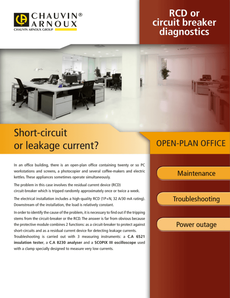
RCD or circuit breaker diagnostics Short-circuit or leakage current? In an office building, there is an open-plan office containing twenty or so PC workstations and screens, a photocopier and several coffee-makers and electric kettles. These appliances sometimes operate simultaneously. The problem in this case involves the residual current device (RCD) circuit-breaker which is tripped randomly approximately once or twice a week. The electrical installation includes a high-quality RCD (1P+N, 32 A/30 mA rating). Downstream of the installation, the load is relatively constant. In order to identify the cause of the problem, it is necessary to find out if the tripping stems from the circuit-breaker or the RCD. The answer is far from obvious because the protective module combines 2 functions: as a circuit-breaker to protect against short-circuits and as a residual current device for detecting leakage currents. Troubleshooting is carried out with 3 measuring instruments: a C.A 6521 insulation tester, a C.A 8230 analyser and a SCOPIX III oscilloscope used with a clamp specially designed to measure very low currents. OPEN-PLAN OFFICE Insulation test with the C.A 6521 megohmmeter An insulation test carried out with a C.A 6521 insulation tester does not reveal any significant faults. Tests on the equipment connected to the electrical network show, by a process of elimination, that these appliances are not the direct cause of the problem. There is no detectable dysfunction downstream of the installation. Monitoring with the C.A 8230 recorder-wattmeter The C.A 8230 is connected to the electrical cabinet downstream of the RCD. In this way, it can be used for a preliminary instant visual check on the current and voltage. The current’s waveform is distorted (non-sinusoidal). This distortion, due to harmonics present on the network, is entirely normal when the loads connected are taken into account. The recordings can be used to determine the office’s current consumption and thus check that the circuit-breaker is correctly calibrated and can support the load. Fig.1 There is a Min value visible caused by tripping of the RCD. Fig.2 Fig.3 An initial RMS current monitoring campaign is run over a period of 2 hours with sampling at 1 s intervals (Fig. 2). The MN93A current sensor is connected to the phase and the trend curves show that the 30 A threshold is regularly exceeded The second measurement campaign extends over 2 days, with sampling every 20 s (Fig. 3). The recording over a period of 2 days shows the various peak values reached during a day. Did you know? The circuit breaker For a short time when starting up, a load requires a brief overcurrent which may be more than ten times its rated operating current. This overcurrent, which is normal, must nevertheless not trip the protective system. So the circuit-breakers are designed to be capable of absorbing a current peak higher than the protection threshold for a short time. In the event of a smaller but longer overcurrent, however, the system will logically cut off the power supply. t In 3 5 10 Measurement of the load inrush current The data below are acquired when all the equipment is started up simultaneously. In motor Inrush mode, the C.A 8230 is set with a 30 A threshold. When the RCD is reset, the protective module is immediately tripped. As we can see (Fig. 4), the current is cut off after 392 ms. Peak current at 58.4 A. 100 ms Fig.5 Fig.4 Analysis of the motor-inrush recording produced by the C.A 8230 shows (Fig. 5) a peak current of 58 A, with a max. measured current of 30.1 A. This value is acceptable for the circuit-breaker during the inrush phase (see "Did you know?"). The curve also shows that the rated current stabilizes at approximately 30 A after 100 ms. This means that the circuit-breaker can be ruled out as the cause when one or more loads are started up. Monitoring with the Scopix III oscilloscope At the same time, the current clamp connected to the SCOPIX III is set up around the phase and the neutral. The current is measured in one-shot mode by the SCOPIX (sampling at 2.5 GS/s per channel in one-shot mode). The wide dynamic range for input offered by the SCOPIX III (156 µV/div to 200 V/div) provides excellent accuracy for low-value measurements. In a single-phase system, the electric current flowing in an electrical installation must be the same in the phase conductor and in the neutral conductor. Any difference between these 2 values means that there is leakage. The capture obtained here on the screen of the SCOPIX (Fig. 6) very clearly shows a leakage current exceeding the 30 mA threshold. This value is sufficient to trip the RCD each time. The RCD The principle of a residual current device or RCD is based on comparison of the currents flowing in the different conductors. In a single-phase system, the device checks the current flowing in the phase conductor and the current flowing in the neutral conductor. If the device detects a difference between the 2 values, it means there is a leakage current flowing to the earth of the installation. The RCD is tripped immediately, thus protecting any people present against possible electrocution. Fig.6 Low-cost solution? This type of problem is increasingly frequent due to equipment and linear loads which give rise to leakage currents. When a large number of PCs are grouped on a single electrical feeder, it increases the risks. To solve this problem of intermittent tripping, the installation’s switchboard can be doubled so that all the loads are spread in a balanced way on 2 identical RCDs of equal power (32 A / 30 mA). Measuring instruments used SCOPIX III 5 in 1: Oscilloscope, multimeter, FFT analyser, harmonic analyser and recorder • 12-bit converter to provide excellent resolution for measuring low currents • 2 or 4 isolated channels • 40 to 200 MHz bandwidth (depending on the model) with bandwidth limiter (15 MHz, 1.5 MHz or 5 kHz) C.A 6521 Insulation tester at 500 V • Dual analogue and digital display • Measurements up to 2 G • Automatic detection of dangerous voltages • Continuity (buzzer) FRANCE Chauvin Arnoux 190, rue Championnet 75876 PARIS Cedex 18 Tel : +33 1 44 85 44 85 Fax : +33 1 46 27 73 89 info@chauvin-arnoux.fr www.chauvin-arnoux.fr UNITED KINGDOM Chauvin Arnoux Ltd Unit 1 Nelson Ct, Flagship Sq, Shaw Cross Business Pk Dewsbury, West Yorkshire - WF12 7TH Tel : +44 1924 460 494 Fax : +44 1924 455 328 info@chauvin-arnoux.co.uk www.chauvin-arnoux.com middle east Chauvin Arnoux Middle East P.O. BOX 60-154 1241 2020 JAL EL DIB (Beirut) - LEBANON Tel : +961 1 890 425 Fax : +961 1 890 424 camie@chauvin-arnoux.com www.chauvin-arnoux.com 906211263 - Ed. 1 - 06/2011 Non-contractual document C.A 8230 Power and energy quality analyser • Inrush up to 18 s • Harmonics from the 1st to the 50th order: THD-r, THD-f • Single-phase and balanced three-phase wattmeter • Simultaneous display of waveforms for current and voltage • Automatic recognition of the sensor connected


