vii TABLE OF CONTENTS CHAPTER
advertisement

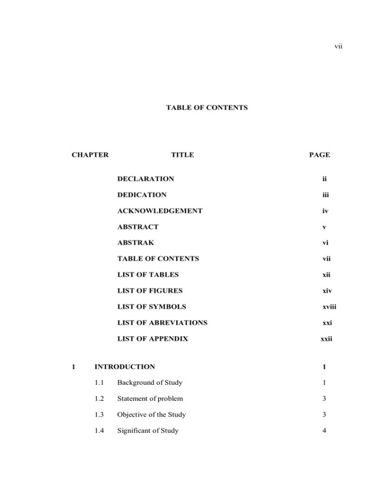
vii TABLE OF CONTENTS CHAPTER 1 TITLE PAGE DECLARATION ii DEDICATION iii ACKNOWLEDGEMENT iv ABSTRACT v ABSTRAK vi TABLE OF CONTENTS vii LIST OF TABLES xii LIST OF FIGURES xiv LIST OF SYMBOLS xviii LIST OF ABREVIATIONS xxi LIST OF APPENDIX xxii INTRODUCTION 1 1.1 Background of Study 1 1.2 Statement of problem 3 1.3 Objective of the Study 3 1.4 Significant of Study 4 viii 1.5 2 Scopes of the Study 4 LITERATURE REVIEW 5 2.1 Introduction 5 2.2 Cutting Tool Material 6 2.2.1 Tool Material for Precision Machining 6 2.2.2 Super Hard Materials and Tools 8 2.2.3 Technology of CVD Diamond Coated Grinding Tools 12 2.3 2.4 2.5 Diamonds 15 2.3.1 Natural Diamond 16 2.3.2 Synthetic Diamonds 16 2.3.3 Polycrystalline Diamonds 17 Substrates 17 2.4.1 Tungsten Carbide 18 2.4.2 19 Role of Cobalt in Cemented Tungsten Carbide CVD Coating Methods 2.5.1 Hot Filament Chemical Vapor Deposition (HFCVD) 21 22 2.5.2 Microwave Plasma Enhanced Chemical Vapor Deposition (MPECVD) 2.5.3 D.C. Plasma Jet CVD 26 27 2.5.4 Comparison of the Hot Filament Method with Other Methods 2.6 27 Pretreatment 28 2.6.1 Chemical Pretreatment 29 ix 2.7 2.8 2.9 2.10 3 2.6.2 Bias Enhanced Nucleation (BEN) 36 2.6.3 Interlayer (1-5μm) 37 2.6.4 Heat Treatment 38 2.6.5 Scratching and Seeding Pretreatment 39 Nucleation and Growth 40 2.7.1 Surface Engineering Approach 40 Diamond Grain Size 41 Adhesion Strength 43 2.9.1 Adhesion Strength Measurements 43 2.9.2 Residual Stress 45 Summary of Literature 45 RESEARCH METHODOLOGY 59 3.1 Introduction 59 3.2 Detailed Experimental Plan of preliminary Trails 61 3.3 Detailed Experimental Plan for Phase-1 Trails 62 3.4 Detailed Experimental Plan for Phase-2 Trails 64 3.5 Substrate Material 65 3.6 Experimental Equipments 66 3.6.1 Precision Cutting Machine 66 3.6.2 Steam Cleaner 66 3.6.3 Blast Wear Tester (BWT) 67 3.6.4 Weight Balance 67 x 4 3.6.5 Portable Tester 68 3.6.6 Ultrasonic Bath Machine 69 3.6.7 Scanning Electron Microscope (SEM) 69 RESULTS AND DISCUSSIONS 70 4.1 Introduction 70 4.2 Preliminary Results 70 4.2.1 Preliminary Results for Hydrochloric Acid Etching Time 70 4.2.2 Preliminary Results for Murakami Etching Time 72 4.3 Phase-1 Experimental Results 75 4.3.1 Results after Blasting 75 4.3.2 Results after Murakami Etching 79 4.3.3 Results after Acid Etching with HCL Solution 88 4.3.4 Results of Sulfuric Acid Etching 94 4.3.5 Comparing two sulfuric and hydrochloric acid 99 Phase-2 Experimental Results 99 4.4 5 4.4.1 Etching Rate by Murakami Etchant 100 4.4.2 Surface Roughness after Murakami – H2SO4 Etching 102 4.4.3 Surface Morphology after Murakami – H2SO4 Etching 104 4.4.4 Cobalt Contents after H2SO4 Treatment 107 4.4.5 Effect of Murakami Solution 108 CONCLUSIONS AND RECOMMANDATIONS 110 5.1 110 Introduction xi 5.2 Conclusions 110 5.3 Recommendations for Future Works 111 REFERENCES 113 APPENDICES 119 xii LIST OF TABLES TABLE NO. 2.1 TITLE PAGE Comparison between hot hardness, wear resistance and toughness for cutting tool 7 2.2 properties of cutting tool materials 7 2.3 Suitable materials for cutting with diamond and CBN tooling 9 2.4 Comparison of properties of tungsten carbide and other cutting tool materials 19 2.5 Summery of selected literature reviews 46 4.1 Experimental results for part one preliminary trials 71 4.2 Cobalt content after Murakami etching with varied time followed by ten seconds etching with sulfuric acid 74 4.3 Surface roughness values for incoming WC substrates 76 4.4 Surface roughness and weight before/after Murakami’s etching 81 4.5 Percentage of surface roughness increased by Murakami’s etchant 82 4.6 TRR of the WC surface layer by Murakami’s etchant 4.7 Amount of cobalt after first step etching in varied 85 Murakami’s etching time 86 4.8 Surface roughness after Murakami and hydrochloric acid etching 90 4.9 EDAX of WC substrate after etching with solution of xiii hydrochloric acid 93 4.10 Surface roughness after sulfuric acid etching 95 4.11 Surface roughness before and after Murakami’s etching 96 4.12 EDAX data of WC substrate after etching with solution of sulfuric acid 98 4.13 Weight losses for all substrate after chemical etching 100 4.14 Thickness removal rate of the WC surface layer by 4.15 Murakami’s etchant 101 Surface roughness before and after Murakami – H2SO4 etching 103 xiv LIST OF FIGURES FIGURE NO. TITLE PAGE 2.1 Relevance tree for cutting tool 8 2.2 Monocrystal diamond cutting edge 10 2.3 Micro tool with mono crystal diamond 10 2.4 CVD diamond-coated spirals drill, diameter 150 m 11 2.5 Drilled hole diameter 100 m in silicon 11 2.6 Grinding layer with bonded diamond grains D15 12 2.7 CVD diamond grinding layer, schematic cross-section 13 2.8 Grinding wheel after coating 14 2.9 Comparison of hardness of diamond and inorganic materials 15 2.10 Schematic view of the CVD chamber 22 2.11 SEM micrographs of fine grained WC–Co substrates 30 2.12 FWHM of the WC (1 0 0) peak of fine (1 M) and coarse grained (6 M) substrates 31 2.13 SEM micrographs of fine grained substrates 32 2.14 Diamond nucleation densities 33 2.15 The relationship between diamond nucleation densities and the size of diamond particles 2.16 Schematic of the surface engineering approach for fabrication 39 xv of the nano-microcrystalline diamond film composite coating hard metal cutting tools 2.17 41 Schematic of the cross-section of an indention on a diamond -coated cemented carbide substrate 44 3.1 Overall research activities flow chart 59 3.2 Methodology flow chart 60 3.3 The preliminary trials plan 61 3.4 Etching flow chart for phase-1 trials 63 3.5 Etching flow chart for phase-2 trials 65 3.6 WC substrate material after cutting from rod 65 3.7 Precision cutting machine 66 3.8 Harnisch+Rieth D-S 100A steam cleaner 67 3.9 Blast wear tester (BWT) 67 3.10 DHAUS weight balance 68 3.11 Portable surface roughness tester 68 3.12 Brain Sonic 12 Ultrasonic Bath 69 3.13 Scanning electron microscope (SEM) equipped with EDX 69 4.1 Cobalt contents versus of hydrochloric acid etching time 71 4.2 SEM micrograph of the WC substrate after cutting 72 4.3 SEM micrographs of WC–Co substrates 73 4.4 Cobalt content verses of Murakami’s etching time 74 4.5 SEM micrograph of the blasted samples 75 4.6 Surface of samples before and after blasting 77 4.7 Surface roughness’s of all samples before and after blasting 77 xvi 4.8 Weight losses during the blasting process 78 4.9 Cobalt content for incoming WC and blasted substrate 78 4.10 Surface morphology of WC substrate after Murakami etching 80 4.11 Slightly increased in surface roughness of tungsten carbide 82 4.12 The increment of surface roughness by Murakami’setchant 82 4.13 Weight losses at different Murakami etching time 83 4.14 TRR of WC surface by Murakami’s etchant 86 4.15 SEM micrographs of WC–Co substrates morphologies 87 4.16 EDAX of WC substrate after first step etching for 3 minutes 87 4.17 SEM micrographs of WC–Co substrates after being etched 89 4.18 Substrates surface roughness before and after HCL acid 90 4.19 Surface roughnesses before and after HCL etching 91 4.20 EDAX of WC substrate etched for 20 minutes with Murakami 92 4.21 Cobalt content after hydrochloric acid etching 93 4.22 SEM micrographs of WC–Co substrates 94 4.23 WC surface roughnesses before and after sulfuric acid 95 4.24 WC surface roughness’s before and after Murakami 96 4.25 EDAX of WC substrate submitted 3 minute with Murakami 97 4.26 Cobalt content after sulfuric acid etching 99 4.27 The effect of different acid solution (HCL and H2SO4) 99 4.28 TRR of WC surface layers by Murakami’s etchant 102 4.29 Average samples roughness before and after pretreatment 103 4.30 Surface roughness for all samples versus the Murakami 104 4.31 SEM micrographs of WC–Co samples 105 xvii 4.32 SEM micrographs of WC–Co samples after Murakami 106 4.33 EDAX of WC substrate submitted 20 minute with Murakami 107 4.34 Cobalt content versus of Murakami’s etching time 108 4.35 Magnification 2500X (a) and magnification 5000X (b) 109 xviii LIST OF SYMBOLS °K - Kelvin degree Ag - Silver Al2O3 - Aluminum oxide Au - Gold CH4 - Methane Co - Cobalt CrC - Chromium carbide Gm - Gram GPa - Giga Pascal H2 - Hydrogen H2O - Water H2O2 - Hydrogen peroxide H2SO4 - Sulfuric acid H3PO4 - Hydro phosphoric acid HCl - Hydrochloride acid HF - Hydrofluoric acid HNO3 - Nitric acid m - Weight xix Mg - Magnesium Mo - Molybdenum Nb - Niobium Ni - Nickel NiCr - Nickel chromium Nm - Nanometer Pt - Platinum Ra - Average roughness Ry - The peak-to-valley height Rz - Ten-point height S - Area Sa - Section area Si3N4 - Silicon nitride SiC - Silicon carbide Ta - Tantalum TiAlN - Titanium aluminum nitride TiC - Titanium carbide TiCN - Titanium carbide-nitride TiN - Titanium nitride V - Volume WC - Tungsten carbide WC-Co - Co-cemented tungsten carbide ZrN - Zirconium nitride - Delta xx m - Micrometer wc - Bulk density of tungsten carbide wc-co - Bulk density of Co cemented tungsten carbide xxi LIST OF ABBREVIATIONS a-C - Amorphous carbon BEN - Bias Enhanced Nucleation CVD - Chemical Vapor Deposition DOC - Depth-Of-Cut HFCVD - Hot Filament Chemical Vapor Deposition HP-HT - High Pressure High Temperature MCD - Microcrystalline Diamond MMCs - Metal Matrix Composites MPECVD - Microwave Plasma Enhanced Chemical Vapor Deposition NCD - Nano-Crystalline Diamond PACVD - Plasma Assisted Chemical Vapor Deposition PCBN - Polycrystalline Cubic Boron Nitride PCD - Polycrystalline Diamond PVD - Physical Vapor Deposition SEM - Scanning Electron Microscope TMCVD - Time-Modulated Chemical Vapor Deposition TRR - Thickness Removal Rate XRF - X – Ray Fluorescenc xxii LIST OF APPENDICES APPENDIX TITLE PAGE A SEM micrographs after hydrochloric etching 119 B EDAX analysis of WC after hydrochloric acid etching 122 C SEM micrographs after sulfuric acid etching 128 D EDAX analysis of WC after sulfuric acid etching 129 E SEM micrographs after sulfuric acid etching 131 F EDAX of WC after sulfuric acid etching without blasting 133


