Enhancing User Immersion and Natural interaction in HMD based Virtual
advertisement

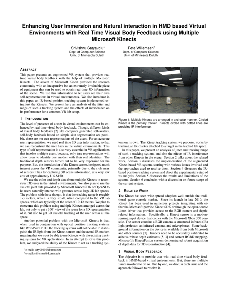
Enhancing User Immersion and Natural interaction in HMD based Virtual Environments with Real Time Visual Body Feedback using Multiple Microsoft Kinects Srivishnu Satyavolu∗ Pete Willemsen† Dept. of Computer Science Univ. of Minnesota Duluth Dept. of Computer Science Univ. of Minnesota Duluth A BSTRACT This paper presents an augmented VR system that provides real time visual body feedback with the help of multiple Microsoft Kinects. The advent of Microsoft Kinect provided the research community with an inexpensive but an extremely invaluable piece of equipment that can be used to obtain real time 3D information of the scene. We use this information to let users see their own self-representations in virtual environments. We also introduce in this paper, an IR-based position tracking system implemented using just the Kinects. We present here an analysis of the jitter and range of such a tracking system and the effects of interference on its performance for a common VR lab setup. 1 I NTRODUCTION The level of presence of a user in virtual environments can be enhanced by real time visual body feedback. Though, different kinds of visual body feedback [2] like computer generated self-avatars, self-body feedback based on simple skin segmentation are possible, these are not true representations of the users. For an accurate user representation, we need real time 3D user information, so that we can reconstruct the user back in the virtual environments. This type of self representation is also very essential in VR applications that involve multiple users, because, only true representations will allow users to identify one another with their real identities. The traditional depth sensors turned out to be very expensive for the purpose. But, the introduction of the Kinect sensor, instigated much interest across the VR community, primarily due to the rich array of sensors it has for capturing 3D scene information, at a very low cost of approximately U.S.$150. We use the color and depth data from multiple Kinects to reconstruct 3D user in the virtual environments. We also plan to use the skeletal joint data provided by Microsoft Kinect SDK or OpenNI to let users naturally interact with gestures across large 3D lab spaces. The problem with these though, is that the tracking range is roughly 1-3 meters, which is very small, when compared to the VR lab spaces, which are typically of the order of 10-12 meters. We plan to overcome this problem using multiple Kinects arranged across the lab, not only to get a 360◦ view of the scene for a 3D representation of it, but also to get 3D skeletal tracking of the user across all the space. Another potential problem with the Microsoft Kinects is that, when used in conjunction with optical position tracking systems like WorldViz PPTH, the tracking systems will not be able to distinguish the IR light from the Kinect sensor and the actual IR marker, meaning that we wont be able to use Kinects with the existing tracking systems for VR applications. In an attempt to solve this problem, we analyzed the ability of the Kinect to act as a tracking sys∗ e-mail: saty0010@d.umn.edu † e-mail:willemsn@d.umn.edu Figure 1: Multiple Kinects are arranged in a circular manner. Circled Kinect is the primary tracker. Kinects circled with dotted lines are providing IR interference. tem on its own. The Kinect tracking system we propose, works by tracking an IR-marker attached to a target in the tracked lab space. In this paper, we present an analysis of jitter and tracking range of such a tracking system, and also the effects of IR interference from other Kinects in the scene. Section 2 talks about the related work, Section 3 discusses the implementation of the augmented Kinect-based VR system, starting with various issues involved and the approaches used to resolve them, Section 4 discusses the IRbased position tracking system and about the experimental setup of its analysis, Section 5 discusses the results and limitations of the system. Section 6 concludes with a discussion on future scope of the current system. 2 R ELATED W ORK The Kinect has seen wide-spread adoption well outside the traditional game console market. Since its launch in late 2010, the Kinect has been used in numerous projects integrating with either the Microsoft-provide Kinect SDK or through the open-source Linux driver that provides access to the RGB camera and depthrelated information. Specifically, a Kinect sensor is a motionsensing input device that comes with the Microsoft Xbox 360 console. The sensor contains a RGB camera, a structured infrared (IR) light projector, an infrared camera, and microphones. Some background information on the device is available from both Microsoft and other sources [7]. Kinects need to be accurately calibrated to acheive robust depth estimates [5, 3] and correct RGBD mapping. Microsoft’s KinectFusion system demonstrated robust acquisition of depth data for 3D reconstruction [4]. 3 V ISUAL B ODY F EEDBACK The objective is to provide user with real time visual body feedback in HMD-based virtual environments. But, there are multiple issues involved to do so. One by one, we discuss each issue and the approach followed to resolve it. 3.1 RGBD Mapping and 3D Point Cloud For a given scene, Kinect’s RGB and depth sensors provide separate streams ( 640x480 pixels ), that by default, are not mapped together. This is because the RGB and IR camera are not calibrated together, and the images obtained by these are at a small offset that varies from one Kinect to another. Also, the RGB camera has a slightly larger field of view than the IR camera, resulting the images to be in different scales of one another. To get an accurate RGBD mapping, we used RGBDemoV0.4, Nicholas Burrus’ implementation of OpenCV Chessboard Recognition techniques for stereo camera calibration. Yet, another problem is that the values reported by the depth camera are raw depth disparity values and are not real world depths. Raw depth values typically range from [0, 2047], with 2047 representing invalid depths. So, we used Stephane Magnetat’s depth conversion function that converts these raw depth disparity values into meters. This allows us to represent the entire scene as a colored 3D point cloud. The following equations obtained from Nicholas Burrus and Stephane Magnetat’s posts help us get the point cloud: zworld = 0.1236 ∗ tan(dim /2842.5 + 1.1863) xworld = (ximage − cxd ) ∗ zworld / f xd yworld = (yimage − cyd ) ∗ zworld / f yd where f xd , f yd , cxd and cyd are the intrinsics of the depth cam0 era. Then, reprojected 3D point on the color image Pworld is: 0 Pworld = R ∗ Pworld + T 0 xrgb = (xworld ∗ f xrgb /z0world ) + cxrgb yrgb = (y0world ∗ f yrgb /z0world ) + cyrgb where R and T are the rotation and translation parameters estimated during the stereo calibration. 3.2 User Representation and Segmentation using multiple Kinects From the 3D point cloud of the scene, we aim to extract user(s) from the background. Color-based segmentations wont work very well here because, ideally, we would want to extract the user information under any lighting conditions. Hence, we employed depth-based background subtraction techniques instead. This includes applying a series of OpenCV image morphological operations like erode, close etc., to remove any noise that might be present in the source and destination depth images. The resulting depth image contains depths of only the foreground objects which in our case would be the user(s). This image is then used as a mask to obtain just those 3D points that correspond to the user(s) in the scene. These 3D points are used to obtain triangles that finally represent the user in the scene. But, the user representation obtained above corresponds just to a single view. To obtain a 360◦ view of the user, the point clouds from multiple Kinects should be merged together into the same virtual environment. In order to do that, multiple Kinects can be calibrated with one another using any of the various calibration programs like Nicholas Burrus’ RGBDemoV0.6, Oliver Kreylos’ KinectViewer or manual calibration. Oliver Kreylos’ KinectViewer is semi-automated, in the sense that, it requires manual identification of points that should be given to a point alignment program. We used our Kinect based position tracking system to capture the points for us and then used those points to be aligned using Oliver Kreylos’ point alignment program. Figure 2 shows two different views of the segmented user using two Kinects. Figure 2: Merged User Representation based on two Kinects. 4 T RACKING P OSITIONS WITH K INECTS We analyze the Kinects ability to robustly track an IR marker across the space of a 7m x 10m lab, focusing on the jitter of position data acquired over distance and in the presence of multiple Kinect sensors that potentially can cause severe IR interference. The overall objective of this work is to understand the efficacy of using multiple Microsoft Kinects as tracking devices for monitoring a users position and a users skeletal system in a VR application. While a single Kinect is capable of tracking an IR light within the lab, multiple Kinects afford different views of users within the tracked space that are not possible using a single Kinect. Combining multiple views can strengthen skeletal tracking mechanisms provided by APIs such as Microsofts Kinect SDK or the OpenNI framework. However, these APIs effective ranges are limited to about 2 to to 3 meters, which could limit usable mobility in VR applications, where more typical tracking ranges from 10 to 12 meters in size. Understanding the tracking range of the Kinect is an important factor to consider for using Kinects for position tracking. The operational range of skeletal tracking APIs is limited, likely because the depth resolution of the Kinect decreases with increase in distance from the Kinect. Hence, it becomes difficult to estimate skeletal joint positions as users get farther away. The tracking system described in this paper exploits the fact that, even though its difficult to estimate the entire set of skeletal positions after a certain range, its still possible to get reliable depth values enough to get an estimate of the users position across a large lab space. To get reliable position tracking, we use a single IR marker attached to the users head that can be tracked over a large space. While this section focuses on IR tracking, we specifically test the sensitivity of the tracking to IR interference from multiple Kinects. The reason why interference from multiple Kinects may be an issue involves using multiple Kinects to improve skeletal tracking. With multiple Kinects, IR projectors will potentially project structured IR light into the scene and possibly into other Kinect IR sensors. In theory, this interference could cause problems with the depth values from the Kinect. Some research has been done to reduce interferences by using a Kinect-shuttering approach [6, 1]. Our experiments specifically focus on testing the Kinect-based IR tracking system against interference from multiple Kinects. 4.1 Tracking IR Marker There are a couple of issues that need to be resolved inorder to obtain the maker world position. First, the IR marker creates its own small circle of IR interference that makes it difficult to precisely identify it in the IR image. Moreover, interference from the other Kinects does cause problems for detecting the IR marker. In these situations, our software can get confused between the actual IR marker and the bright IR interference from the additional Kinects. To overcome these issues, we apply locality of neighborhood and static background separation techniques. Background depth information of the entire scene is captured by merging depth images of the same scene obtained over time. The acquisition of the background depth image is done once upon starting the tracker system. The background image is used to extract foreground images in real time by a simple background separation Figure 3: Top left image is from RGB camera; top right image is depth information collected about static background; bottom left is the current depth image with the tracked object; and bottom right is foreground depth information subtracted from the depth image. technique using OpenCV. A series of OpenCV image morphological operations are performed on the extracted foreground depth and IR images to remove any external noise. These images can now be used to extract the posi tion and depth information of the IR marker. Each IR image from the Kinect is analyzed in real time to find the brightest pixel in the foreground (in this case, our IR marker). Figure 3 illustrates the segmented depth information during this process. Pixel depth is calculated using a locality of neighborhood principle which estimates the IR marker depth value by examining the surrounding pixels outside the small circle of interference of the IR marker in the depth image. Using a 15 by 15 pixel neighbor hood window, to calculate the mean of all the valid depths, worked well for this implementation. Real world IR marker positions are then computed from the extracted raw values, using equations listed in Section 3.1. 4.2 Experimental Setup Our experimental setup consists of 5 Kinects mounted on chairs of same height, with one being the primary Kinect (Figure 1) while the remaining introduce interference. They are all arranged to provide tracking centered around a 7m by 7m space. We used a WorldViz IR marker mounted on a cart as the tracked point. The primary Kinect is calibrated as given in Section 2, and the tracked space consists of 30 manually placed points, that are roughly a meter apart from each other. At each point, 1000 samples of the IR marker positions are collected which are then averaged to get the final estimate of the tracked position. This is done both with and without interference from the other Kinects. The entire step is repeated for all the 30 points. The jitter in these IR marker positions is then analyzed over all the 1000 samples with and without interference. 5 R ESULTS AND D ISCUSSION Figure 4 compares the tracked positions with and without interference. The green circles represent the estimates of the points measured without interference, while the red crosses represent the estimates of the points measured with interference from other Kinects. Standard deviations of reported pixel positions were nearly zero in all cases except for some points show in the figure, where the interference is maximum. The mean and standard deviations of a single point with maximized in terference was a mean depth value of 1016.0 (SD=89.6723). Without interference at this location, the mean depth value was 1039.6 (SD=1.0484). Additionally, when compared with our WorldViz PPTH system the Kinect was roughly off by 3cm on average. The above results suggest that effect of interference is almost negligible. The few points in the Figure 4, where the interference was maximum, are those points that are very close to the Kinects Figure 1. Also, the jitter of the positions reported by the Kinect are uniform through all the depths. There are a few limitations with our current system though. For instance, it’s very difficult to track more than one IR marker and thereby multiple users. One possible way of overcoming this limitation to some extent would be to use skeletal joints to compensate Figure 4: Comparison of the kinect tracking data aligned with data acquired from a World Viz PPTH Tracking system. the need for multiple markers and by using spatio-temporal information of those joints/markers to distinguish between IR markers on different users. Another limitation is that, as the current Kinect hardware supports just one of RGB or IR streams to be used, it’s not possible to provide visual body feedback and also tracking with the help of same Kinect. Therefore, some Kinects have to be used solely for tracking while the others can be used to provide visual body feedback. 6 C ONCLUSION We observed that interference is not a major concern for IR tracking with multiple Kinects. Thus, we believe that, based on our initial experiments, the Kinect can serve as a low cost tracking system. Also, with the help of Microsoft SDK or OpenNI skeletal tracking capability multiple Kinects can be used to implement a more functional tracking system that allows multiple users to not only see themselves in real time but also interact with one another using natural gestures across VR lab spaces. In addition, it should even be possible to get orientation data of the user based on the skeletal joint information. R EFERENCES [1] K. Berger, K. Ruhl, C. Brümmer, Y. Schröder, A. Scholz, and M. Magnor. Markerless motion capture using multiple color-depth sensors. In Proceedings of Vision, Modeling and Visualization (VMV), pages 317– 324, 2011. [2] K. R. K. H. Gerd Bruder, Frank Steinicke. Enhancing presence in headmounted display environments by visual body feedback using headmounted cameras. [3] C. D. Herrera, J. Kannala, and J. Heikkilä. Accurate and practical calibration of a depth and color camera pair. In Proceedings of International Conference on Computer Analysis of Images and Patterns (CAIP), pages 437–445, 2011. [4] S. Izadi, D. Kim, O. Hilliges, D. Molyneaux, R. Newcombe, P. Kohli, J. Shotton, S. Hodges, D. Freeman, A. Davison, and A. Fitzgibbon. Kinectfusion: Real-time 3d reconstruction and interaction using a moving depth camera. In Proceedings of ACM Symposium on User Interface Software and Technology (UIST), pages 559–568, 2011. [5] K. Khoshelham. Accuracy analysis of kinect depth data. In ISPRS Workshop on Laser Scanning 2011, 2011. [6] Y. Schröder, A. Scholz, K. Berger, K. Ruhl, S. Guthe, and M. Magnor. Multiple kinect studies. Technical Report 09–15, ICG, TU Braunschweig, 2011. [7] J. Smisek, M. Jancosek, and T. Pajdla. 3d with kinect. Technical report, CTU Prague, 2011.


