Fiber Loss Budgets
Document ID: 12221
Contents
Introduction
Prerequisites
Requirements
Components Used
Conventions
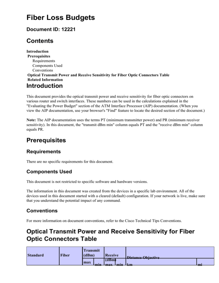
Optical Transmit Power and Receive Sensitivity for Fiber Optic Connectors Table
Related Information
Introduction
This document provides the optical transmit power and receive sensitivity for fiber optic connectors on
various router and switch interfaces. These numbers can be used in the calculations explained in the
"Evaluating the Power Budget" section of the ATM Interface Processor (AIP) documentation. (When you
view the AIP documentation, use your browser's "Find" feature to locate the desired section of the document.)
Note: The AIP documentation uses the terms PT (minimum transmitter power) and PR (minimum receiver
sensitivity). In this document, the "transmit dBm min" column equals PT and the "receive dBm min" column
equals PR.
Prerequisites
Requirements
There are no specific requirements for this document.
Components Used
This document is not restricted to specific software and hardware versions.
The information in this document was created from the devices in a specific lab environment. All of the
devices used in this document started with a cleared (default) configuration. If your network is live, make sure
that you understand the potential impact of any command.
Conventions
For more information on document conventions, refer to the Cisco Technical Tips Conventions.
Optical Transmit Power and Receive Sensitivity for Fiber
Optic Connectors Table
Standard
Fiber
Transmit
(dBm)
Receive
Distance Objective
(dBm)
max
min max min km
mi
MM
ISO/IEC 9314−3
SM cat I
SM cat II
Device
Fiber
−14
−20
−14
−31
2
1.2
−14
−20
−14
−31
14
8.4
0
−4
−15
−37
Type
58
Transmit
Connector (dBm)
max
Catalyst 1900c,
Catalyst 2820
MM
SM
MM
34.8
Receive (dBm)
min
max
min
100BaseFX SC
−14
−19
−14 −33.5
OC−3
SC
−8
−14
−8
OC−3
SC
−32.5 10
MM
MM
Catalyst 5000
Catalyst 2900
(non−XL)
Catalyst 2926
MM
SM
MM
SM
MM
Cisco 1100
concentrator
Cisco 1400
concentrator
SM
MM
SM
Cisco 4000 NPs
MM
SM
SM LR
MM
SM
AIP
MM
SM
MM
FDDI Interface
Processor (FIP)
AGS+ FDDI
applique
ATM Port
Adapters (PAs)
SM
MM
SM
MM
6.2
full−duplex
2;
full−duplex
half−duplex 1.2;
0.4
half−duplex
0.24
2
1.2
Catalyst 3000
MM
Distance
Objective
km mi
100BaseF
SC
10BaseF
SC
100VG
SC
10baseFL
ST
−12
−20
−12 −32.5 2
1.2
OC−3
SC
−8
−14
−8
18
OC−3
SC
−14
−19
−14 −32.5 2
1.2
FDDI
ST
−4
−7
−14 −33
30
18
FDDI
MIC
−14
−18.5 −14 −34
2
1.2
FDDI
ST
−4
−7
−14 −33
30
18
FDDI
FDDI
MIC
MIC
−14
−14
−18.5 −14 −34
−20
−14 −31
2
10
1.2
6.2
FDDI
MIC
−10
−16
2
1.2
OC−3
SC
−8
−18.5 −14 −30
15
9
OC−3
SC
−3
−36
20
12.4
OC−3
SC
−15
−28
3
1.5
OC−3
ST
−8
−15
−14 −31
14.8
9
OC−3
SC
−14
−20
−14 −30
2.4
1.5
TAXI
ST
−14
−20
−14 −31
TAXI
MIC
−10
−16
−10 −27
2
1.2
FDDI
ST
−14
−20
−14 −31
10
6.2
FDDI
OC−3
OC−3
MIC
SC
SC
−10
−8
−14
−16
−15
−20
−10 −27
−8 −31
−14 −30
2
1.2
−32.5 30
−10 −27
(ATM lite)
Fast Ethernet PA
FDDI PA
MM
SM
MM
Packet OC−3
Interface
Processor
(POSIP)
SM IR
MM
SM IR
Cisco 12000
MM
SM IR
MM
155−Mbps
SM
LightStream 100
ATM switch
155−Mbps
MM
100−Mbps
MM
SM IR
SM IR+
LightStream 1010
SM LR
ATM switch
MM
SM IR
SM LR
MM
Catalyst
8540MSR ATM
switch
SM IR
FE
SC
FDDI
SC
−14
−19
−14 −31
15
9.3
FDDI
MIC
−14
−19
−14 −31
2
1.2
OC−3
SC
−8
−15
−8
−31
15
9
OC−3
OC−3
SC
SC
−14
−8
−18.5 −14 −30
−15
−8 −28
3
15
1.5
9.3
OC−3
SC
−14
−20
−14 −26
0.5
0.3
OC−3
SC
−8
−15
−8
−31
15
9.3
OC−3
SC
−14
−20
−14 −26
0.5
0.3
OC−3C
SC
−8
−15
0
−34
OC−3C
SC
TAXI
MIC
OC−3
SC
−8
−15
−8
−30
15
9
OC−3
SC
−3
−8
−3
−32
30
18
OC−3
SC
0
−5
−10 −30
40
25
OC−3
SC
−14
−20
−14 −30
2
1.2
OC−12
SC
−8
−15
−8
−28
15
9
OC−12
SC
2
−3
−8
−28
40
25
OC−12
SC
−14
−20
−14 −26
0.5
0.3
OC−12
SC
−8
−14
−3
−28
15
9
−14
−20
−14 −26
0.5
0.3
−4
−10
0
−17
220/275
meters
720/900
feet
−4
−10
0
−17
550 meters
1800 feet
−3
−9.5
−3
−19
550 meters
1800 feet
−3
−3
−9.5
−9
−3
−3
−19
−19
550 meters
10
1800 feet
6
MM
OC−12
SC
HP Gigabit
62.5/125um
MM SR
Ethernet
1000Base−SXSC
Converters
(GBIC)
HFBR−5601
Cisco
Field−replaceable
unit (FRU)
WS−G5484
50/125um
1000Base−SXSC
HP GBIC
MM
62.5um
SRMM
HFCT−5611 1
LR
1000Base−LX/LH
SC
Cisco FRU
50um MM
WS−G5486
LR
1000Base−LX/LH
SC
9/125um
1000Base−LX/LH
SC
SM LR
Catalyst 8510
Catalyst 8540
MM
100BaseFX SC
−8
−15
−8
−28
.5
1640 feet
MM
100BaseFX MT−RJ
−8
−15
−8
−28
.5
1640 feet
Note:
1
All GBICs use Class 1 lasers, even with multimode fiber. A Mode Conditioning Cable (MCC) is required
when using multimode fiber with any LX/LH GBIC. All of these GBICs have a minimum cable length of two
meters.
Related Information
• ATM Technical Support Page
• LAN & ATM Switches Product Support Page
• Cisco 12000 Series Internet Routers Technical Support Page
• Technical Support − Cisco Systems
Contacts & Feedback | Help | Site Map
© 2014 − 2015 Cisco Systems, Inc. All rights reserved. Terms & Conditions | Privacy Statement | Cookie Policy | Trademarks of
Cisco Systems, Inc.
Updated: Jan 15, 2008
Document ID: 12221


