Troubleshooting Input and Output Errors on
PA−A3 ATM Port Adapters
Document ID: 8631
Contents
Introduction
Prerequisites
Requirements
Components Used
Conventions
PA−A3 Architecture
Input Errors That Use show interface atm Command
Input Errors That Use show controllers atm Command
Output Errors That Use show interface atm Command
Report Interface Errors to the Cisco TAC
Related Information
Introduction
Cisco offers three ATM port adapters for 7500 and 7200 series routers. The PA−A3 port adapter is designed
for use on WAN links that need to implement traffic shaping to control bandwidth on the virtual circuits.
The PA−A3 is also known as ATM Deluxe or Enhanced PA. You can determine whether you have a PA−A3
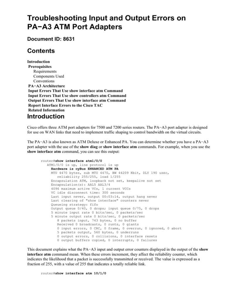
port adapter with the use of the show diag or show interface atm commands. For example, when you use the
show interface atm command, you can see this output:
router#show interface atm1/0/0
ATM1/0/0 is up, line protocol is up
Hardware is cyBus ENHANCED ATM PA
MTU 4470 bytes, sub MTU 4470, BW 44209 Kbit, DLY 190 usec,
reliability 255/255, load 1/255
Encapsulation ATM, loopback not set, keepalive not set
Encapsulation(s): AAL5 AAL3/4
4096 maximum active VCs, 1 current VCCs
VC idle disconnect time: 300 seconds
Last input never, output 00:03:14, output hang never
Last clearing of "show interface" counters never
Queueing strategy: fifo
Output queue 0/40, 0 drops; input queue 0/75, 0 drops
5 minute input rate 0 bits/sec, 0 packets/sec
5 minute output rate 0 bits/sec, 0 packets/sec
8 packets input, 743 bytes, 0 no buffer
Received 0 broadcasts, 0 runts, 0 giants
0 input errors, 0 CRC, 0 frame, 0 overrun, 0 ignored, 0 abort
5 packets output, 560 bytes, 0 underruns
0 output errors, 0 collisions, 0 interface resets
0 output buffers copied, 0 interrupts, 0 failures
This document explains what the PA−A3 input and output error counters displayed in the output of the show
interface atm command mean. When these errors increment, they affect the reliability counter, which
indicates the likelihood that a packet is successfully transmitted or received. The value is expressed as a
fraction of 255, with a value of 255 that indicates a totally reliable link.
router#show interface atm 10/1/0
ATM10/1/0 is up, line protocol is up
Hardware is cyBus ENHANCED ATM PA
MTU 1500 bytes, sub MTU 1500, BW 149760 Kbit, DLY 80 usec,
reliability 249/255, txload 1/255, rxload 1/255
[snip]
Reliability is calculated with the use of this formula:
reliability = number of errors / number of total frames
The show interface output displays the average reliability. Refer to Understanding the Definition of bits per
second (bits/sec) from the show interfaces Command Output for more information.
Note: Refer to Troubleshooting Input Drops on ATM Router Interfaces for more information on how to
troubleshoot input drops on ATM router interfaces.
Prerequisites
Requirements
There are no specific requirements for this document.
Components Used
This document is not restricted to specific software and hardware versions.
Conventions
Refer to Cisco Technical Tips Conventions for more information on document conventions.
PA−A3 Architecture
The PA−A3 uses an ATMizer II segmentation and reassembly (SAR) chip. The output of show controllers
atm command displays the name of the SAR, in this example:
7200−2#show controller atm 3/0
Interface ATM3/0 is up
Hardware is ENHANCED ATM PA − DS3 (45Mbps)
Lane client mac address is 0030.7b1e.9054
Framer is PMC PM7345 S/UNI−PDH, SAR is LSI ATMIZER II
Firmware rev: G119, Framer rev: 1, ATMIZER II rev: 3
idb=0x61499630, ds=0x6149E9C0, vc=0x614BE940
slot 3, unit 2, subunit 0, fci_type 0x005B, ticks 73495
400 rx buffers: size=512, encap=64, trailer=28, magic=4
Curr Stats:
rx_cell_lost=0, rx_no_buffer=0, rx_crc_10=0
rx_cell_len=0, rx_no_vcd=0, rx_cell_throttle=0, tx_aci_err=0
[snip]
The router stores a cell or a reassembled packet in various memory locations. Look at this process in more
detail, with the use of diagrams in order to illustrate the path bits take when they are received from the
physical wire at the PA−A3:
1. When a cell arrives, the framer chip stores the cell in its first−in−first−out (FIFO) memory, which can
contain four 48−byte cells.
2. The cell then moves to the ATMizer SAR cell buffers, which consist of 4 MB transmit (Tx) and 4 MB
receive (Rx) onboard memory or local static random−access memory (SRAM).
3. At this point, the cells take a different path that depends on the hardware version of the PA−A3.
♦ With hardware revision 1.0, the PA−A3 uses the onboard SRAM only as additional cell
storage and forwards the cells across the Peripheral Component Interconnect (PCI) to the
Versatile Interface Processor (VIP) or Network Processing Engine (NPE) host memory,
where it reassembles them.
♦ With hardware revision 2.0, the PA−A3 reassembles the cells in its own memory, rather than
the host memory.
In other words, revision 2.0 uses frame mode and transfers packets from the port adapter to the host
memory, while revision 1.0 uses cell mode and transfers cells to host memory.
Use the show diag command in order to determine the hardware revision of your PA−A3:
router#show diag
PA Bay 1 Information:
ENHANCED ATM OC3 MM PA, 1 ports
EEPROM format version 1
HW rev 2.00, Board revision A0
Serial number: 11535651 Part number: 73−2430−04
Input Errors That Use show interface atm Command
In some cases, incoming cells can be dropped or corrupted, which leads to input errors as displayed in the
output of the show interface atm command. This table explains what each input error counter means.
Error
overrun
Explanation
This is the number of times the FIFO memory of the
framer overruns because of a lack of SAR buffers.
frame
This is the number of times a cell is bad or is
dropped when the framer flushed its overrun FIFO.
abort
This is the number of packet drops caused by cell
throttling at the microcode level to alleviate framing
overruns.
ignored
no buffer
This is the number of packets dropped because a
packet memory buffer was not available or because
the port adapter microcode throttled the virtual
circuit (VC) and stopped accepting new packets.
The receive host buffer can fill when a fast ATM
interface feeds a slower outbound interface.
This is the number of times the ATM interface runs
out of transmit SAR buffers when transmitting
packets over a large number of slow VCs.
This is the number of times that a reassembled
packet fails the AAL5 (ATM adaptation layer)
trailer CRC−32 (cyclic redundancy check), usually
because some cells of the packet are lost due to one
of these reasons:
CRC
• FIFO overrun
• Microcode throttling
• CRC−10 generated via operation,
administration, and maintenance (OAM)
• Network congestion in the ATM switch
cloud
• Real line noise that produces a bit error
Refer to CRC Troubleshooting Guide for ATM
Interfaces for more information.
runts
giants
This is the number of packets that are smaller than a
single cell. Cell corruption by framer Rx FIFO flush
causes this condition.
This is the number of packets that are larger than
the VC maximum transmission unit (MTU). A giant
can be formed when the last cell of a packet is
dropped, so two consecutive packets are
concatenated.
Input Errors That Use show controllers atm Command
The output of show controllers atm command displays several input error counts that also can be used in
order to troubleshoot performance issues on your ATM interface. These counters are highlighted in bold:
7200−2#show controller atm 3/0
Interface ATM3/0 is up
Hardware is ENHANCED ATM PA − DS3 (45Mbps)
Lane client mac address is 0030.7b1e.9054
Framer is PMC PM7345 S/UNI−PDH, SAR is LSI ATMIZER II
Firmware rev: G119, Framer rev: 1, ATMIZER II rev: 3
idb=0x61499630, ds=0x6149E9C0, vc=0x614BE940
slot 3, unit 2, subunit 0, fci_type 0x005B, ticks 73495
400 rx buffers: size=512, encap=64, trailer=28, magic=4
Curr Stats:
rx_cell_lost=0, rx_no_buffer=0, rx_crc_10=0
rx_cell_len=0, rx_no_vcd=0, rx_cell_throttle=0, tx_aci_err=0
[snip]
Counter
rx_cell_lost
Explanation
This is the number of times the SAR
detects lost or mis−inserted cells with the
comparison of the actual or accumulated
payload length to the value of the payload
length field in the AAL5 trailer of the
reassembled packet. The PA−A3 calculates
the accumulated payload length by
multiplying 48 by the number of received
cells since the last cell with the
end−of−AAL5−PDU bit set to one. The
third bit of the payload type identifier [PTI]
field indicates whether the cell is the final
cell of a higher−layer data frame.
Note: This counter currently increments
under very rare circumstances. Cells that
are lost in the ATM network triggers CRC
errors only. Cisco bug ID CSCdu88572
(registered customers only) fixes this.
rx_no_buffer
rx_crc_10
rx_cell_len
rx_no_vcd
This is the number of times that no packet
buffer was available to store an incoming
cell. In this condition, the router drops the
complete packet inside the onboard
memory of PA−A3. Note that the packet
never makes it to the host memory on the
NPE or VIP.
This is the number of times an ATM cell
fails the CRC−10 checksum used by OAM
cells, resource management (RM) cells and
AAL3 or AAL4 packets.
This is the number of times that the
received cell payload length is less than 48
bytes.
This is the number of times that the PA−A3
received a cell without a corresponding
virtual circuit descriptor (VCD) in its local
VC table.
This is the number of times that the PA−A3
microcode does not handle the incoming
rx_cell_throttle cell rate and proactively dropped cells. The
PA−A3 starts throttling the interface if the
total cell buffer usage exceeds a preset high
water mark.
Output Errors That Use show interface atm Command
The output errors counter increments for a PA−A3 interface under these conditions:
• A packet is scheduled for transmission on a VC which is not in the UP status.
• A packet has an invalid or unrecognized virtual circuit descriptor (VCD) number.
• SAR fails to transmit cells to the framer.
• A non−OAM packet uses a VCD value of 0, which is reserved for OAM packets only. The output
counter no longer increments in this condition (CSCdp86348).
• Other miscellaneous reasons, such as interaction with a particular feature
Use the debug atm error command in order to troubleshoot incrementing output errors. Also capture several
outputs of the show controller atm command.
Note: The command debug atm error prints debug output only when it detects an error and normally is not
disruptive to a functioning production router.
When you use a PA−A3 on the 7500 series, you must capture debug atm error and show controller atm
from the console of the Versatile Interface Processor (VIP). Use the if−con command to enter the VIP console
and if−quit in order to exit.
Report Interface Errors to the Cisco TAC
Collect this information before you report input errors to the Cisco Technical Assistance Center:
• Output from the show tech−support command in enable mode so that the running configuration is
included
• Several captures of the show interface atm and show atm vc commands and evidence of the specific
error
• Prepare answers to these questions:
♦ How long has the ATM interface experienced the errors?
♦ When do the input errors increment: throughout periods of high traffic or throughout the day?
♦ Did you add any new protocols or hardware to the router recently?
♦ Did you upgrade the Cisco IOS® software recently?
Related Information
• Troubleshooting Input Queue Drops and Output Queue Drops
• Performance Tuning Basics
• VIP CPU Running at 99% and Rx−Side Buffering
• ATM Technology Support Pages
• More ATM Information
• Technical Support & Documentation − Cisco Systems
Contacts & Feedback | Help | Site Map
© 2014 − 2015 Cisco Systems, Inc. All rights reserved. Terms & Conditions | Privacy Statement | Cookie Policy | Trademarks of
Cisco Systems, Inc.
Updated: Aug 25, 2006
Document ID: 8631


