When Does the no buffer Error Counter Increment
on the PA−A3?
Document ID: 6189
Contents
Introduction
Prerequisites
Requirements
Components Used
Conventions
Buffer−Shortage Drops on the VIP: show queueing interface atm
Related Information
Introduction
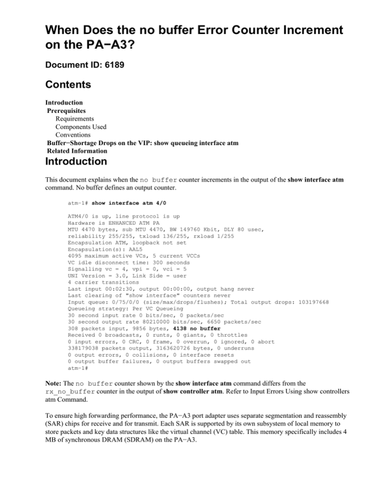
This document explains when the no buffer counter increments in the output of the show interface atm
command. No buffer defines an output counter.
atm−1# show interface atm 4/0
ATM4/0 is up, line protocol is up
Hardware is ENHANCED ATM PA
MTU 4470 bytes, sub MTU 4470, BW 149760 Kbit, DLY 80 usec,
reliability 255/255, txload 136/255, rxload 1/255
Encapsulation ATM, loopback not set
Encapsulation(s): AAL5
4095 maximum active VCs, 5 current VCCs
VC idle disconnect time: 300 seconds
Signalling vc = 4, vpi = 0, vci = 5
UNI Version = 3.0, Link Side = user
4 carrier transitions
Last input 00:02:30, output 00:00:00, output hang never
Last clearing of "show interface" counters never
Input queue: 0/75/0/0 (size/max/drops/flushes); Total output drops: 103197668
Queueing strategy: Per VC Queueing
30 second input rate 0 bits/sec, 0 packets/sec
30 second output rate 80210000 bits/sec, 6650 packets/sec
308 packets input, 9856 bytes, 4138 no buffer
Received 0 broadcasts, 0 runts, 0 giants, 0 throttles
0 input errors, 0 CRC, 0 frame, 0 overrun, 0 ignored, 0 abort
338179038 packets output, 3163620726 bytes, 0 underruns
0 output errors, 0 collisions, 0 interface resets
0 output buffer failures, 0 output buffers swapped out
atm−1#
Note: The no buffer counter shown by the show interface atm command differs from the
rx_no_buffer counter in the output of show controller atm. Refer to Input Errors Using show controllers
atm Command.
To ensure high forwarding performance, the PA−A3 port adapter uses separate segmentation and reassembly
(SAR) chips for receive and for transmit. Each SAR is supported by its own subsystem of local memory to
store packets and key data structures like the virtual channel (VC) table. This memory specifically includes 4
MB of synchronous DRAM (SDRAM) on the PA−A3.
The PA−A3 driver starts incrementing the no buffer counter when the interface exhausts its supply of
local particle buffers. These buffers are tracked with the Tx−BFD number, which you can view in the output
of the show controller atm command.
BFD Cache status:
base=0x62931AA0, size=6144, read=143
Rx Cache status:
Packet buffer descriptor (BFD) describes the index used by the PA−A3 driver to access a specific packet
buffer. The BFD cache size indicates the total number of buffers in the local port adapter (PA) memory. The
current number of free particles is given by the read value.
On the transmit path, the local memory consists of 6144 particles of 576 bytes (or 580 bytes, with an internal
4−byte header that travels with the packet inside the router). Of these, the PA−A3 reserves 144 particles for
system packets like operations, administration, and maintenance (OAM) cells. When the read value reaches
144, the PA−A3 driver starts dropping packets until a sufficient number of local memory particles becomes
available.
No buffer packet drops are different from the OutPktDrops counted in the output of the show atm vc vcd
command. The PA−A3 driver increments the OutPktDrops counter when a VC fills its individual transmit
buffer quota. The purpose of the quota is to prevent a consistently over−subscribed VC from grabbing all of
the packet buffer resources and hindering other VCs from transmitting normal traffic within their traffic
contracts.
An incrementing no buffer counter indicates that the local memory on the PA−A3 simply is exhausted
and does not imply that the VCs have exhausted their per−VC transmit credit.
Prerequisites
Requirements
There are no specific requirements for this document.
Components Used
This document is not restricted to specific software and hardware versions.
The information in this document was created from the devices in a specific lab environment. All of the
devices used in this document started with a cleared (default) configuration. If your network is live, make sure
that you understand the potential impact of any command.
Conventions
For more information on document conventions, refer to the Cisco Technical Tips Conventions.
Buffer−Shortage Drops on the VIP: show queueing interface
atm
In some exceptional situations, the output Versatile Interface Processor (VIP) could have no buffers left to
store a packet that is switched to this output VIP from the Route/Switch Processor (RSP) or from an input
VIP. Consequently, the VIP will need to indiscriminately drop that packet regardless of its precedence.
Such an exceptional situation could occur as a result of heavy congestion combined with misconfiguration of
the weighted random early detection (WRED) parameters. As an example, if the exponential weighting
constant has been reconfigured from the default value to an excessively large value, then the WRED
algorithm is slow to react to congestion (because the moving average increases only slowly as the
instantaneous queue fills up). Thus, WRED may not start its intelligent discard early enough and the bursts
keep filling the buffers.
You should avoid these situations, because these drops indiscriminately affect high precedence traffic.
Drops on the VIP due to buffer shortage can be monitored through the show queueing interface atm
command through the nobuffer drops counter.
7513−1−31# show queueing interface atm 11/0/0.103
VC 5/103 −
ATM11/0/0.103 queue size 46
packets output 1346100, drops 134315, nobuffer drops 0
WRED: queue average 44
weight 1/512, max available buffers 1021
Precedence 0: 40 min threshold, 81 max threshold, 1/10 mark weight
1344366 packets output, drops: 134304 random, 10 threshold
Precedence 1: 45 min threshold, 81 max threshold, 1/10 mark weight
(no traffic)
Precedence 2: 50 min threshold, 81 max threshold, 1/10 mark weight
(no traffic)
Precedence 3: 55 min threshold, 81 max threshold, 1/10 mark weight
(no traffic)
Precedence 4: 60 min threshold, 81 max threshold, 1/10 mark weight
(no traffic)
Precedence 5: 65 min threshold, 81 max threshold, 1/10 mark weight
(no traffic)
Precedence 6: 70 min threshold, 81 max threshold, 1/10 mark weight
1734 packets output, drops: 0 random, 1 threshold
Precedence 7: 75 min threshold, 81 max threshold, 1/10 mark weight
(no traffic)
The nobuffer drops counter indicate how many packets have been dropped indiscriminately by the VIP,
because no buffer was available at that time to accept the packet when it was handed over to the output VIP
by the RSP or by the VIP that received the packet. Because the VIP drops the packet without being able to run
the IP to ATM class of service (CoS) featureand, in fact, without even looking at the packet at allsuch
packets are dropped irrespective of the moving average queue occupancy for the particular VC and
irrespective of the packet precedence.
In addition to the show queueing interface command, you can use the show vip hqf command to display the
number of nobuffers on a PA−A3 in a Cisco 7500 series router.
VIP−Slot0# show vip hqf
!−−− Output suppressed.
qsize 1525 txcount 46810 drops 0 qdrops 0 nobuffers 0
aggregate limit 2628 individual limit 657 availbuffers 2628
weight 1 perc 0 ready 1 shape_ready 1 wfq_clitype 0
For more detailed information about Buffer−Shortage Drops on the VIP, refer to IP to ATM Class of Service
Phase 1 Design Guide.
Related Information
• Input Errors Using show controllers atm Command
• IP to ATM Class of Service Phase 1 Design Guide
• Cisco ATM Port Adapter
• ATM (Asynchronous Transfer Mode) Support Pages
• Technical Support − Cisco Systems
Contacts & Feedback | Help | Site Map
© 2014 − 2015 Cisco Systems, Inc. All rights reserved. Terms & Conditions | Privacy Statement | Cookie Policy | Trademarks of
Cisco Systems, Inc.
Updated: Nov 15, 2007
Document ID: 6189


