MICROPOWER ENERGY HARVESTING FOR INEAR DEVICES A. Delnavaz and J. Voix
advertisement

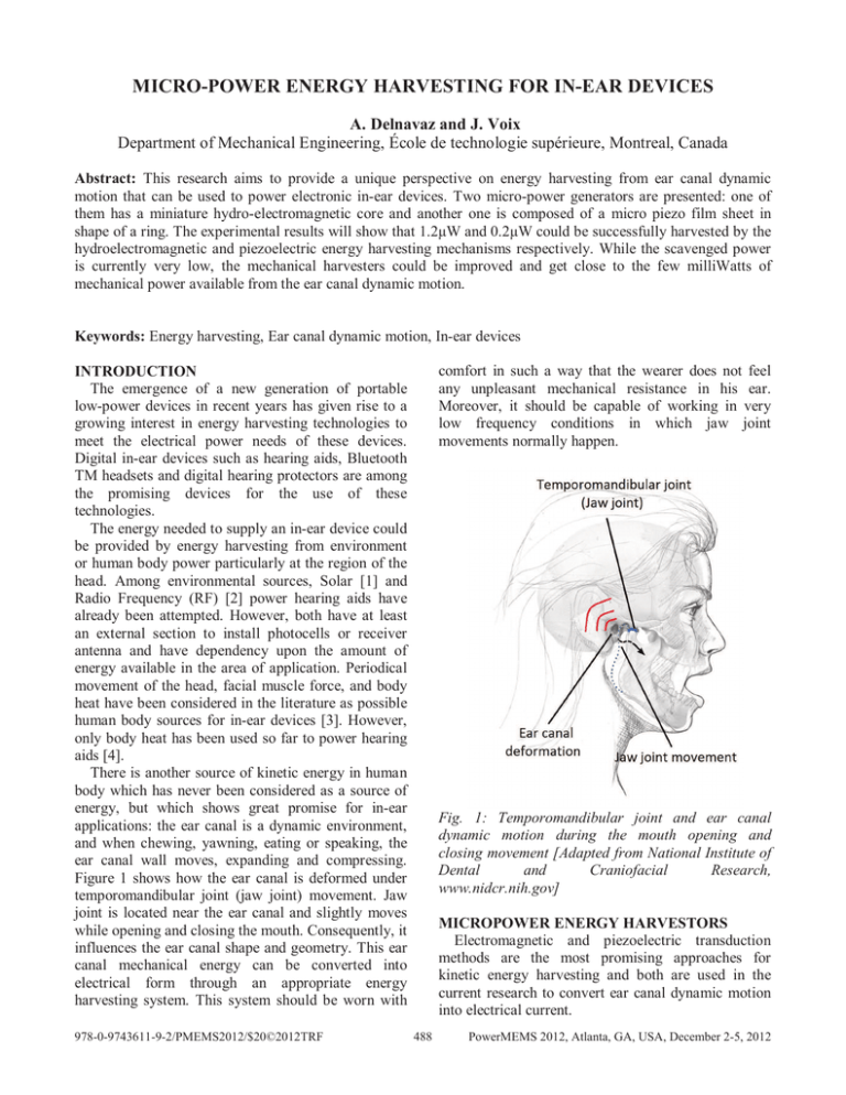
MICRO­POWER ENERGY HARVESTING FOR IN­EAR DEVICES A. Delnavaz and J. Voix Department of Mechanical Engineering, École de technologie supérieure, Montreal, Canada Abstract: This research aims to provide a unique perspective on energy harvesting from ear canal dynamic motion that can be used to power electronic in-ear devices. Two micro-power generators are presented: one of them has a miniature hydro-electromagnetic core and another one is composed of a micro piezo film sheet in shape of a ring. The experimental results will show that 1.2µW and 0.2µW could be successfully harvested by the hydroelectromagnetic and piezoelectric energy harvesting mechanisms respectively. While the scavenged power is currently very low, the mechanical harvesters could be improved and get close to the few milliWatts of mechanical power available from the ear canal dynamic motion. Keywords: Energy harvesting, Ear canal dynamic motion, In-ear devices comfort in such a way that the wearer does not feel any unpleasant mechanical resistance in his ear. Moreover, it should be capable of working in very low frequency conditions in which jaw joint movements normally happen. INTRODUCTION The emergence of a new generation of portable low-power devices in recent years has given rise to a growing interest in energy harvesting technologies to meet the electrical power needs of these devices. Digital in-ear devices such as hearing aids, Bluetooth TM headsets and digital hearing protectors are among the promising devices for the use of these technologies. The energy needed to supply an in-ear device could be provided by energy harvesting from environment or human body power particularly at the region of the head. Among environmental sources, Solar [1] and Radio Frequency (RF) [2] power hearing aids have already been attempted. However, both have at least an external section to install photocells or receiver antenna and have dependency upon the amount of energy available in the area of application. Periodical movement of the head, facial muscle force, and body heat have been considered in the literature as possible human body sources for in-ear devices [3]. However, only body heat has been used so far to power hearing aids [4]. There is another source of kinetic energy in human body which has never been considered as a source of energy, but which shows great promise for in-ear applications: the ear canal is a dynamic environment, and when chewing, yawning, eating or speaking, the ear canal wall moves, expanding and compressing. Figure 1 shows how the ear canal is deformed under temporomandibular joint (jaw joint) movement. Jaw joint is located near the ear canal and slightly moves while opening and closing the mouth. Consequently, it influences the ear canal shape and geometry. This ear canal mechanical energy can be converted into electrical form through an appropriate energy harvesting system. This system should be worn with 978-0-9743611-9-2/PMEMS2012/$20©2012TRF Fig. 1: Temporomandibular joint and ear canal dynamic motion during the mouth opening and closing movement [Adapted from National Institute of Dental and Craniofacial Research, www.nidcr.nih.gov] MICROPOWER ENERGY HARVESTORS Electromagnetic and piezoelectric transduction methods are the most promising approaches for kinetic energy harvesting and both are used in the current research to convert ear canal dynamic motion into electrical current. 488 PowerMEMS 2012, Atlanta, GA, USA, December 2-5, 2012 Table 1: Hydroelectromagnetic energy harvester parameters Parameters Unit Value Tube diameter mm 2 Moving magnet diameter mm 1.6 Moving magnet height mm 6.4 Fixed magnet height mm 3.2 Coil mean diameter mm 6 Coil height mm 2 Wire thickness µm 40 Number of turns 1000 Coil ohmic resistance Ω 214 Hydroelectromagnetic energy harvester A hydroelectromagnetic system is composed of a magnet element in a thin tube filled with water that is surrounded by 40µm copper wire with 1000 turns coil. One end of the tube is attached to an expandable earplug. By injecting water into the system using a water filling syringe, the earplug expands to perfectly fit against the ear canal walls of the wearer. At the same time, the water level rises in the tube and the water sinks the magnet. By placing a second magnet fixed in such a way that the same poles face each other, a repulsive force is produced that can suspend the first free magnet inside the tube, as shown in Fig. 2. The voltage of the load resistor for three consecutive mouth opening and closing cycles is shown in Fig. 3. Fig. 3: The voltage of the load resistor (•• ) in hydroelectromagnetic setup The power transferred to the load resistor is calculated as follows and is shown in Fig. 4. • ••! ൌ " (1) in which " is the load resistance which is also equal to the resistance of the coil. In this figure, the maximum generated power is about 2.5µW. By averaging the generated power in a cycle of mouth opening and closing, the mean generated power would be 1.2µW. Fig. 2: Hydroelectromagnetic energy harvesting system As ear canal volume changes, the water level in the tube rises and falls. Consequently, the suspended magnet moves and induces voltage in the coil. The geometrical parameters of the prototype system are listed in Table 1. To conduct actual measurements, a human subject worn the prototype system and jaw joint movements were applied while the voltage of the load resistor (•• ) was measured. The load resistance was set equal to the coil resistance in order to ensure maximum power transfer. Fig. 4: Instantaneous power transferred to the load resistor in hydroelectromagnetic setup 489 because the capacitance of the piezo-ring and resistance of the probe constitute a potential divider that biases the oscilloscope’s readings. As an alternative method, the average output power can be calculated indirectly. In this method, the charge produced by the piezo-ring is stored in a capacitor of known capacitance. By measuring the voltage of the capacitor under charge, it is possible to estimate how much power has been generated. In the proposed measuring setup (Fig. 5) a voltage source in series with the capacitance #$ represents the piezo ring. The charge generated from ear canal dynamic motion is stored in a load capacitor #% using a fullwave rectifier circuit as depicted in Fig. 5. Each cycle of jaw joint movement consists of two phases: 1) jawopening and 2) jaw-closing phases. During the jawopening phase two forward-biased diodes (D1 and D3) let the generated current flow. During the jaw closing phase the direction of current is reversed and #% is charged through reversed-biased diodes (D2 and D4). By using this configuration, the voltage across #% increases twice in each cycle. The generated charge in each phase is divided between the internal and the load capacitors considering their capacitances. Jaw joint movement is supposed to have a constant periodic cycle, hence the generated charge at each phase is always the same and has a value of & . Then at each new phase, & is redistributed between #$ and #% . Assuming #% #$ and considering •' as a forward biased voltage drop of diodes the voltage of the load capacitor at the (th phase is obtained by [6] Piezoelectric energy harvester The piezoelectric power generator includes a ring made of a piezo film sheet that surrounds the earpiece in contact with the ear canal walls. The piezo film is a flexible sheet of polyvinylidene fluoride (PVDF) that is metalized by a silver ink coating [5]. This ring is fabricated by cutting a piece of piezo film sheet in a T-shape. The tips of the “T” cross are joined to make the shape of a ring and its stem forms a tail that is connected to wires. This piezo-ring is folded on the earpiece that is itself mounted on a headset and is placed inside the subject’s ear canal as shown in Fig. 5. The headset keeps the ring in position and prevents it from escaping from the ear canal during jaw joint movement. By opening and closing the mouth, the piezo-ring is deformed and generates an electrical charge. ሺሻ ൌ Fig. 5: Piezoelectric energy harvesting system $ − Ͷ' * ! − " +ͳ − # % ʹ* ! " (2) By measuring the voltage of the capacitor in phase & and knowing the other parameters, this equation can be solved for '. Finally, the generated power can be calculated by A prototype piezo-ring was hand-made to fit the same ear canal previously presented in the hydroelectromagnetic section. The geometrical parameters of the piezo-ring are listed in Table 2. () ൌ Table 2: Piezoelectric energy harvester parameters Parameters Unit Value Ring diameter mm 10 Ring height mm 7 Piezo film thickness µm 110 Permittivity Fm-1 3.2 Capacitance nF 0.18 The generated power depends on the output voltage of the piezo-ring. As it turns out, this voltage cannot be directly measured by an oscilloscope probe, 490 ͳ '* ʹ +, (3) in which - is the frequency of producing charges in each phase that is twice the frequency of jaw opening and closing cycle. The circuit shown in Fig. 5 was used with low forward voltage drop Schottky diodes and a low leakage ceramic capacitor with the capacitance of +. ൌ ʹͶ/0 . The measured forward voltage drop of Schottky diodes was 12 ൌ ͲǤͶ1 and their inverse leakage currents were measured to be less than ͲǤͳ&3 at ͶǤͷ1. Consecutive jaw opening and closing cycles were applied to the system for hundred seconds and the results are represented in Fig. 6. This figure shows that the voltage of the load capacitor rises exponentially, and reaches around ͲǤͲ1 after 150 full cycles of the jaw opening and closing movement. The frequency of jaw joint movement was ͳͷͲȀ ͳͲͲ ൌ ͳǤͷ45, that is equal to the frequency of jaw activities in the hydro-electromagnetic test. The mean produced charge in each phase is estimated to be ' ൌ ͷ&+ . Using Eq. 3, the generated power is approximately () ൌ ͲǤʹ/(. REFERENCES [1] A. Carr, “Solar-powered hearing aids invented,” CBC news ­ Health, 2011. [Online]. Available: http://www.cbc.ca/news/health/story/2011/09/ 12/medical-inventions.html. [Accessed: 15Sep-2011]. [2] F. Wu and S. L. Tomasson, “RF Power Supply for Hearing Aids,” U.S. Patent US2009/0214064 A12009. [3] E. Goll, H.-P. Zenner, and E. Dalhoff, “Upper bounds for energy harvesting in the region of the human head.,” IEEE transactions on bio­ medical engineering, vol. 58, no. 11, pp. 3097–103, Nov. 2011. [4] A. Lay-Ekuakille, G. Vendramin, and A. Trotta, “Design of an energy harvesting conditioning unit for hearing aids.,” Conference proceedings : ... Annual International Conference of the IEEE Engineering in Medicine and Biology Society. IEEE Engineering in Medicine and Biology Society. Conference, vol. 2008, pp. 2310–3, Jan. 2008. [5] Measurement Specialties Inc., “Piezo Film Product Type and Price List,” www.meas­ spec.com. [6] A. Cuadras, M. Gasulla, and V. Ferrari, “Thermal energy harvesting through pyroelectricity,” Sensors and Actuators A: Physical, vol. 158, no. 1, pp. 132–139, Mar. 2010. Fig. 6: Charging a 24µF capacitor by in­ear piezo­ ring energy harvesting mechanism versus full cycle of jaw opening and closing movement. CONCLUSION Energy harvesting from ear canal dynamic motion was investigated in this paper in order to power the electronic circuits of in-ear devices. Hydroelectromagnetic and piezoelectric energy harvesting systems were proposed to convert the mechanical movement of the ear canal walls to the electric current. The hand-made electromagnetic system produced a cycle-averaged power of 1.2µW while the hand-made piezoelectric system produced 0.2µW on average. Both systems prove that it is possible to use ear canal dynamic motion as a human body source of power. The scavenged power is currently very low and could be explained by the fact that the proposed mechanical harvesters are handmade non-optimal systems. By improving these harvesters and further integrating them into in-ear devices, it would be possible to give the wearer of such electronic devices more time between battery changes or charges and therefore increase the autonomy and ease-of-use of electronic in-ear devices. 491


