AUTONOMOUS TUNABLE ENERGY HARVESTER Ivo N. Ayala
advertisement
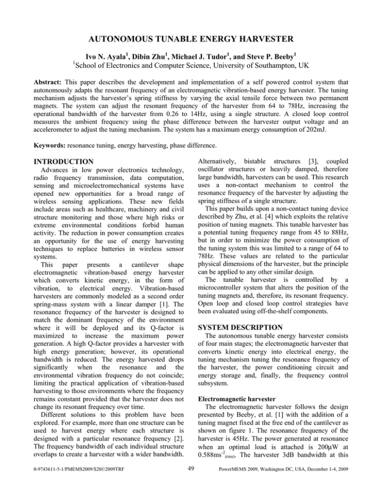
AUTONOMOUS TUNABLE ENERGY HARVESTER 1 Ivo N. Ayala1, Dibin Zhu1, Michael J. Tudor1, and Steve P. Beeby1 School of Electronics and Computer Science, University of Southampton, UK Abstract: This paper describes the development and implementation of a self powered control system that autonomously adapts the resonant frequency of an electromagnetic vibration-based energy harvester. The tuning mechanism adjusts the harvester’s spring stiffness by varying the axial tensile force between two permanent magnets. The system can adjust the resonant frequency of the harvester from 64 to 78Hz, increasing the operational bandwidth of the harvester from 0.26 to 14Hz, using a single structure. A closed loop control measures the ambient frequency using the phase difference between the harvester output voltage and an accelerometer to adjust the tuning mechanism. The system has a maximum energy consumption of 202mJ. Keywords: resonance tuning, energy harvesting, phase difference. Alternatively, bistable structures [3], coupled oscillator structures or heavily damped, therefore large bandwidth, harvesters can be used. This research uses a non-contact mechanism to control the resonance frequency of the harvester by adjusting the spring stiffness of a single structure. This paper builds upon a non-contact tuning device described by Zhu, et al. [4] which exploits the relative position of tuning magnets. This tunable harvester has a potential tuning frequency range from 45 to 88Hz, but in order to minimize the power consumption of the tuning system this was limited to a range of 64 to 78Hz. These values are related to the particular physical dimensions of the harvester, but the principle can be applied to any other similar design. The tunable harvester is controlled by a microcontroller system that alters the position of the tuning magnets and, therefore, its resonant frequency. Open loop and closed loop control strategies have been evaluated using off-the-shelf components. INTRODUCTION Advances in low power electronics technology, radio frequency transmission, data computation, sensing and microelectromechanical systems have opened new opportunities for a broad range of wireless sensing applications. These new fields include areas such as healthcare, machinery and civil structure monitoring and those where high risks or extreme environmental conditions forbid human activity. The reduction in power consumption creates an opportunity for the use of energy harvesting techniques to replace batteries in wireless sensor systems. This paper presents a cantilever shape electromagnetic vibration-based energy harvester which converts kinetic energy, in the form of vibration, to electrical energy. Vibration-based harvesters are commonly modeled as a second order spring-mass system with a linear damper [1]. The resonance frequency of the harvester is designed to match the dominant frequency of the environment where it will be deployed and its Q-factor is maximized to increase the maximum power generation. A high Q-factor provides a harvester with high energy generation; however, its operational bandwidth is reduced. The energy harvested drops significantly when the resonance and the environmental vibration frequency do not coincide; limiting the practical application of vibration-based harvesting to those environments where the frequency remains constant provided that the harvester does not change its resonant frequency over time. Different solutions to this problem have been explored. For example, more than one structure can be used to harvest energy where each structure is designed with a particular resonance frequency [2]. The frequency bandwidth of each individual structure overlaps to create a harvester with a wider bandwidth. 0-9743611-5-1/PMEMS2009/$20©2009TRF SYSTEM DESCRIPTION The autonomous tunable energy harvester consists of four main stages; the electromagnetic harvester that converts kinetic energy into electrical energy, the tuning mechanism tuning the resonance frequency of the harvester, the power conditioning circuit and energy storage and, finally, the frequency control subsystem. Electromagnetic harvester The electromagnetic harvester follows the design presented by Beeby, et al. [1] with the addition of a tuning magnet fixed at the free end of the cantilever as shown on figure 1. The resonance frequency of the harvester is 45Hz. The power generated at resonance when an optimal load is attached is 200μW at 0.588ms-2(rms). The harvester 3dB bandwidth at this 49 PowerMEMS 2009, Washington DC, USA, December 1-4, 2009 to 2.4V at which point it consumes 156mA. It should be noted that the minimum start up voltage for the actuator is 2.6V. Once moving, 2.4V is sufficient to maintain actuation. The penalty for reducing operating voltage is the reduced thrust achievable by the actuator. level of acceleration is 0.26Hz. The harvester has been optimized to operate at low frequencies and low acceleration levels; it has been fabricated using conventional manufacturing processes and discrete components with a total volume of 1120mm3. Beam Power generation magnets Voltage multiplier and energy storage The harvester generates an A.C. voltage from 0.15 to 0.6Vpeak which is insufficient to operate the linear actuator, the control subsystem or the application electronics. Therefore, it is necessary to rectify and increase the voltage to a minimum level that enables the operation of these systems. A Dickson voltage multiplier (VM) has been designed; the circuit increases the input voltage and at the same time rectifies it. The VM implemented has 5 stages and uses Schottky diodes (BAT754L) that provide low forward bias voltage. The conditioned power output is stored within a supercapacitor, i.e. the energy storage. The voltage at the supercapacitor (Vc) must reach 2.6V for the actuator to operate and it should not drop below 2.4V when in operation. A small capacitor will reach the desirable level in a short time but will not store enough energy to operate the actuator for long periods. A large capacitor will increase the time taken to reach 2.6V. The actuator maximum linear travel to adjust the resonance frequency between 64 to 78Hz is 2mm, which corresponds to 0.5s actuator operation consuming 202mJ. Under these conditions, a 0.55F (GS-206 from CAP-XX) capacitor experiences a voltage drop of 137mV still allowing the actuator to operate correctly. Additionally, this capacitor can provide high peak currents and the 156mA required by the actuator is well within the rated value. Copper coil Tuning magnet Steel keeper Tungsten mass Fig 1: Tunable electromagnetic micro-harvester Tuning mechanism The tuning mechanism consists of a pair of magnets, one fixed at the free end of the cantilever, while a second magnet is mounted on a movable structure aligned to the beam. The tuning magnets have been aligned to create an attractive force between them. The distance between the magnets is adjusted using a linear actuator, thus the axial force exerted on the cantilever is varied. Figure 2 presents the tuning mechanism setup. Generator Tuning magnet Control subsystem The control subsystem consists of four modules; microcontroller, actuator driver, sensing and cold start-up. PIC16F884 microcontroller was chosen for its low power consumption and high current source capability of 25 mA, which provides the option to power external electronic components directly from any of its ports. The linear actuator is driven by the microcontroller using a double H-bridge circuit using 8 control lines, instead of normal 4. This modification allows the actuator to be driven directly from Vc using a combination of P/N MOSFETs. Two parameters are sensed within the system: ambient frequency and acceleration. These are monitored using the output of the harvester itself and an additional accelerometer. They provide the control subsystem with the information necessary in case an adjustment of resonant frequency is required. Finally, the cold start- Actuator 15mm Fig 2: Tuning mechanism setup The linear actuator uses a bipolar stepper motor (LC1574W from Haydon) with a linear travel of 20μm per step. The actuator combines low power and low voltage characteristics suitable for this solution. The power consumption has been reduced from its rated value by reducing the operating voltage from 4 50 0.55 Phase difference (degrees) 80.0 RESONANCE CONTROL The environment frequency is measured indirectly from the harvester output signal. The signal is passed through a zero level detector that decouples and converts the input into a square wave. Using the capture mode feature in the microcontroller, the period of 8 consecutive cycles is averaged to reduce error. Ambient acceleration is also measured using an accelerometer (LIS3L06AL, STMicroelectronics). This sensor was not used to measure frequency directly because at the acceleration level at which the system was tested, 0.588ms-2(rms), the output signal is too small (∼100mVp-p), resulting in unacceptable quantization errors at the microcontroller’s analogueto-digital converter. The relation between the harvester resonant frequency and the distance between tuning magnets was determined experimentally and an algorithm was created and stored in the microcontroller. The algorithm relates the measured ambient frequency to the ideal position of the actuator, i.e. it matches the harvester resonant frequency to the ambient. When there is a positional difference (Xdiff) higher than ±60μm, or ±3 steps, between the calculated optimal and current position, the actuator will move to the optimal position. Fine tuning is achieved with a closed loop control. This was implemented by measuring the phase difference (θdiff) between the output of the harvester and the accelerometer. This technique has been adapted from methods used in vibration absorption [6]. The value and sign of the phase difference provide the amount and direction required by the fine tuning. The harvester is at resonance when θdiff becomes zero, in this case the microcontroller adjusts the tuning magnets until θdiff is <±20° which is the maximum tuning possible given the resolution of the actuator. Figure 3 shows how the voltage and θdiff varies around resonance. When θdiff is <±20°, the system enters a low power mode where the microcontroller goes into sleep mode and all the electronic components powered directly from the microcontroller are de-energized: sensor, Hbridges, external circuitry. The microcontroller is programmed to periodically measure the frequency at the harvester and adjust the position of the tuning magnets as described. The time between frequency measurements is 320s and this is controlled using the Watchdog Timer (WDT) feature 60.0 0.5 40.0 20.0 0.45 0.0 -20.0 0.4 -40.0 -60.0 0.35 Phase difference -80.0 Harvester -100.0 Harvester output voltage (Vrms) 100.0 up circuitry disables the microcontroller while Vc is below 2.0V avoiding its erratic behavior previously observed [5]. 0.3 -160 -120 -80 -40 0 40 80 120 160 Distance from resonant position (μm) Fig. 3: Phase difference in the microcontroller. When the time expires, the WDT resets the microcontroller, returning from sleep to normal mode. Next, the microcontroller checks Vc by using the microcontroller’s internal voltage reference feature (Vref), which is equal to 0.6V and is independent of the microcontroller’s supply voltage, in this case Vc. Vref is converted to a digital reading using the microcontroller’s 10-bits ADC. The maximum ADC value corresponds to a voltage equal to Vc. Therefore, as Vc reduces, the digital value of Vref increases, and vice versa. The threshold value for the digital Vref is specified to correspond to a Vc which is equal or higher than 2.6V. EXPERIMENTAL RESULTS It has been found experimentally that to achieve the 64 to 78Hz tuning range the distance between tuning magnets should vary from 3 to 5mm. This range of magnets displacement maximizes the resonance tuning range. The magnets are not moved closer than 3mm because beyond this the force between the tuning magnets increases the total damping reducing the power output [4]. Resonance tuning The autonomous tunable harvester was experimentally tested varying the ambient frequency with an acceleration of 0.588ms-2(rms). Figure 4 shows the harvester output voltage when the ambient frequency changes from 64 to 78Hz. While the harvester is tuned at 64Hz the output voltage remains at 1.2Vp-p. When the ambient frequency changes to 78Hz the output voltage reduces after a few seconds to 156mVp-p. Next, the harvester automatically retunes itself to 78Hz increasing the output voltage to 1.2Vp-p, the same value as before. 51 Tuned @ 64Hz Harvester output Voltage (V) 0.7 Re-Tuned @ 78Hz Initial charge The tunable energy harvester has been tested starting with Vc= 0V. The supercapacitor is charged by the harvester, at 0.588ms-2(rms), through the VM. The supercapacitor rises from 0V to 2.6V in 35hrs. 0.5 Not Tuned 0.3 0.1 -0.1 CONCLUSION AND FUTURE WORK -0.3 This paper has presented a fully autonomous tunable energy harvester that adjusts its resonance frequency to coincide with the ambient frequency. This is the first reported tuning device that operates exclusively on the energy harvester. The system is appropriate for environments where small and infrequent frequency changes occur due to the large recovery time required for large frequency changes. The system is currently being further optimized to increase the energy harvested while reducing the energy consumed. -0.5 -0.7 -7 0 7 14 21 28 35 42 Time (sec) Fig. 4: Resonance control, frequency changes from 64Hz to 78Hz. Recovery time The recovery time is defined as the time needed by harvester to collect the energy used during tuning. This is measured through the voltage variation at the supercapacitor. The greater Xdiff, the larger amount of energy required by the actuator to adjust the harvester resonance frequency. Using the capacitor previously described, the voltage drops 137mV after a 2mm adjustment, which represents an adjustment of 14Hz in the harvester resonance frequency. The harvester requires 2.11hrs to harvest the energy used during this tuning process, as shown in figure 5. Table 1 presents the recovery time for different Xdiff. 1.5 1.4 1.3 1.2 1.1 1 0.9 0.8 0.7 0.6 0.5 0.4 0.3 0.2 0.1 0 2.6 2.55 2.5 2.45 2.4 2.35 Storage Harvester 2.3 -0.2 0 0.2 0.4 0.6 0.8 1 1.2 1.4 1.6 1.8 2 REFERENCES [1] Beeby S, Torah R, Tudor M, Glynne-Jones P, O’Donnell T, Saha C, Roy S 2007 A micro electromagnetic generator for vibration energy harvesting J. Micromech. Microeng. 17 1257-65 [2] Ferrari M, Ferrari V, Guizzetti M, Marioli D, Taroni A 2008 Piezoelectric multifrequency energy converter for power harvesting in autonomous Microsystems Sensor and Actuators A:Physical 142 329-35 [3] Ramlan R, Brennan M, Mace B, 2008 Nonlinear bistable mechanism for energy harvesting devices Proc. EURODYN 2008 (Southampton, UK, 7-9 July 2008) [4] Zhu D, Roberts S, Tudor M, Beeby S 2008 Closed Loop Frequency Tuning of a VibrationBased Microgenerator Technical Digest PowerMEMS 2008 (Sendai, Japan, 9-12 November 2008) 229-32 [5] Torah R, Tudor M, Patel K, Garcia I, Beeby S 2007 Autonomous Low Power Microsystem Powered by Vibration Energy Harvesting IEEE Sensor 2007 (Atlanta, USA, 28-31 October 2007) 264-7 [6] Brennan M, 2006 Some recent developments in adaptive tuned vibration absorbers/neutralisers Shock and Vibration 13 531-43 Harvester output Voltage (Vrms) Storage capacitor Voltage(VDC) 2.65 ACKNOWLEDGMENTS Ivo N. Ayala would like to acknowledge the support from CONACyT (Mexico) through scholarship 197176/302242. 2.2 Time (hrs) Fig. 5: 14Hz mistuning. Xdiff (μm) 20 80 160 800 2000 Frequency variation (Hz) 0.13 0.5 1 4 14 Recovery time (min) 4.16 4.45 10.06 35.73 126.60 Voltage drop (mV) 3.84 6.12 12.04 44.66 137.00 Table. 1: Recovery time. 52
