EDGES M #123 MASSACHUSETTS INSTITUTE OF TECHNOLOGY
advertisement
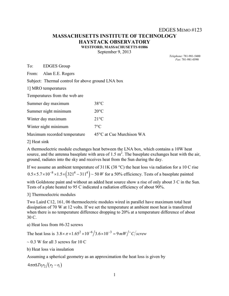
EDGES MEMO #123 MASSACHUSETTS INSTITUTE OF TECHNOLOGY HAYSTACK OBSERVATORY WESTFORD, MASSACHUSETTS 01886 September 9, 2013 To: EDGES Group From: Alan E.E. Rogers Telephone: 781-981-5400 Fax: 781-981-0590 Subject: Thermal control for above ground LNA box 1] MRO temperatures Temperatures from the web are Summer day maximum 38°C Summer night minimum 20°C Winter day maximum 21°C Winter night minimum 7°C Maximum recorded temperature 45°C at Cue Murchison WA 2] Heat sink A thermoelectric module exchanges heat between the LNA box, which contains a 10W heat source, and the antenna baseplate with area of 1.5 m2. The baseplate exchanges heat with the air, ground, radiates into the sky and receives heat from the Sun during the day. If we assume an ambient temperature of 311K (38 °C) the heat loss via radiation for a 10 C rise ( ) 0.5 × 5.7 ×10−8 ×1.5 × 3214 − 3114 ~ 50 W for a 50% efficiency. Tests of a baseplate painted with Goldstone paint and without an added heat source show a rise of only about 3 C in the Sun. Tests of a plate heated to 95 C indicated a radiation efficiency of about 90%. 3] Thermoelectric modules Two Laird C12, 161, 06 thermoelectric modules wired in parallel have maximum total heat dissipation of 70 W at 12 volts. If we set the temperature at ambient most heat is transferred when there is no temperature difference dropping to 20% at a temperature difference of about 30 C. a) Heat loss from #6-32 screws The heat loss is 3.8 × π ×1.652 ×10⁻⁶ 3.6 ×10−3 = 9 mW C screw ~ 0.3 W for all 3 screws for 10 C b) Heat loss via insulation Assuming a spherical geometry as an approximation the heat loss is given by 4πσ∆Tr1r2 ( r2 − r1 ) 1 Where r1 = radius of LNA box ~ 10 cm r2 = radius of outer box ~ 20 cm ∆T = temperature difference σ = conductivity ~ 0.04 For ∆T = 25 C the heat loss is approximately 3 W A check of the estimate can be made just considering the LNA cover which is 15×16 cm and is only 1 cm below the cover of the box. If we assume an insulation conductivity of ~0.04 the heat transfer will be about 2.4 W for 25 C temperature difference. c) Heat conduction to baseplate The conduction of heat to the baseplate using a circular plate approximation given by σ 2π d ∆T log e ( r2 r1 ) Where σ=conductivity = 204 W/m-K r1= radius of heat source ~ 5 cm r2= Outer radius of plate ~ 60 cm d = thickness of plate ~ 1.3 cm ∆t = temperature difference from center to outer edge of plate For a 10 C difference the heat carried away to the plate is 67 W. d) LNA temperature Given the loss in efficiency of the modules and the added heat transfer losses we can only cool the LNA to about 25 C below ambient. If we set the LNA to 25 C we may be able to just handle the highest temperatures expected at Boolardy provided the baseplate stays below 50 C. We could gain added margin on the high end by increasing the temperature to 30 C. A higher temperature also has the advantage of avoiding condensation when below the temperature is below the dew point. However the LNA box is packed with insulation so that little air will be available to produce condensation. In addition, we may want to seal the box with silicone (RTV). In order to account for extreme conditions oven industries 5RG-900 controller set point temperature can be overridden by the controller. An interface is provided by a FTDI/USB dongle using a c-coded function. A USB power control switch is also needed to avoid thermal run away in the event of a failure of the controller or thermoelectric assembly. 4) Tests of thermoelectric assembly a) Initial test As an initial test the thermoelectric assembly was run with no heat source on the cold plate and a heater on the hot plate. The following results were obtained: 2 Power into assembly (%) 0 75 85 Hot plate temperature (C) 25 55 62 ∆TC 0 30 37 The controller was set for temperature 25 C and 12 volts. The maximum current was 5 amp or 60 W power. This test is consistent with the expected performance given the thermal loss through the screws and thermal resistance of the plate connections via thermal grease. The ∆T of 37 C was larger than the maximum ∆T of about 30 C that I was able to obtain with the Laird DA-075-12-02 assembly. b) Test to simulate high temperatures Tests designed to simulate the Boolardy environment were made using a hairdryer to heat the air around the LNA box while running the EDGES LNA gave the following results: Box temperature C 26 34 38 43 46 Thermoelectric power % -5 -27 -58 -65 -75 The negative sign indicates that the thermoelectric modules are cooling the LNA. c) Temperature differentials These temperature differentials were measured with LNA operating. Location ∆T K Thermoelectric controller thermistor reference Box near thermistor Rear of front section with LNA Front of LNA at input connector Top cover of box Bottom of outer box enclosure (-50% power) 0 +0.2 +0.3 +1.3 +0.9 +15 The reason for the increased temperature in the front section containing the LNA is because this section contains major power source. Much of the power comes from the coax switch so that it is important to have the 3-position switch running for complete thermal equilibrium which takes about 5 hours after power up the electronics. The use of a latching switch was investigated but no switch was found competitive with reliability of the Dowkey 401U-2Z08 whose lifetime is expected to exceed 5 million cycles. To minimize the power a capacitive charge circuit (see Figure 1 of memo #116) is used to reduce the average power while still providing the critical 3 specified current to switch from antenna to load. Figure 1 shows the mechanical schematic of the thermoelectric assembly and Figure 2 shows the details of the thermal plates. Figure 3 shows the DC wires to the thermoelectric modules, Klizon switch to open the circuit in the event of temperature exceeding about 68 C and the wires to the thermistor used by the controller to sense the temperature. Thermistor is coated with thermal paste and sealed into a 0.5” deep hole in the side of the plate. Figure 4 shows the LNA in the enclosure which is insulated using mostly 0.75” R-4.0. Figure 5 shows the enclosure open with the cover. Figure 6 shows the cable from the LNA coming out of the enclosure and Figure 7 shows the controller with an RFI filter. The circuit diagram is shown in Figure 8. Comments on a future improvement This totally above ground scheme has the disadvantage that the thermoelectric modules have to cover an extreme temperature range. A much better scheme, which should be possible at another site, is to exchange heat with the ground as described in memo #119. In this case the LNA box could still be located on the antenna baseplate. The air circulation through a pipe only a few feet deep would provide air whose temperature would change little between day and night and going to more than 10 feet would take out most of the seasonal cycle. Added notes and precautions 1] If the thermal unit is run in the lab it can go into a thermal run-away because as the unit cools the cold plate the overall dissipation increases with increasing temperature difference. In order to test in the lab the unit should be placed on a large baseplate or it should be placed on a block under each end so that a fan can be placed underneath to cool the base. 2] When installing LNA avoid excessive force downwards or sideways. While the thermoelectric modules can withstand pressures of several hundred psi they cannot with stand forces which want to bend over the semiconductor structures between the plates. 3] When removing the LNA loosen the screws completely and then wiggle the LNA box while applying force to remove the LNA and the thermal paste will gradually allow air to enter to release the effects of atmospheric pressure. 4] While the LNA box bottom has flattened to get good even contact it is still important to get an even layer of thermal paste over the entire area to minimize the voltage difference between the LNA and the thermistor. With care it is possible to move the thermistor to the LNA but given good thermal contact this will only provide a small improvement in overall performance. 5] Thermal paste is needed between the enclosure base and the antenna baseplate. The most critical region is the area which includes the 4 countersunk screws which attach the enclosure base to the thermoelectric module hot plate. 4 Figure 1. Shows the mechanical schematic of the thermoelectric assembly. 5 Figure 2 6 Figure 3. Klixon over temperature switch and thermistor on edge of cold plate. Thermistor which is on the end of the thin twisted line is inserted into a 0.5” hole lined with thermal paste and sealed in place with RTV. 7 Figure 4. Photo of LNA box in thermal enclosure. The box is attached to the cold plate with 4 allen head screws. There is thermal paste between the bottom of the box and the cold plate. 8 Figure 5. LNA box in enclosure with LNA cover in place and enclosure top open. 9 Figure 6. Rear of enclosure. Following installation the small square metal cover through which the cable exists will be sealed with RTV to prevent moisture and insects from entering the enclosure. 10 Figure 7. Oven industries thermoelectric controller and filter box to attenuate the RFI from the controller. These units will be located in the RFI enclosure in the equipment hut along with the PC. 11 Figure 8. Circuit diagram of thermal control electronics. 12

